
The RF power sensor contains a temperature sensor for compensating the temperature dependence of the diode forward voltage and leakage current and maybe also some other, minor effects like the temperature coefficient of the reference voltage source and the temperature dependency of the input current of the ADC.
In order to compensate all these temperature effects, one has to perform ADC readings at different temperatures and at different frequencies and RF power levels.
But how? Of course, I don’t have a climate chamber at home. But I do have an oven in my kitchen, and I was seriously considering placing the RF power sensor in the oven and determining the temperature coefficient by varying the oven temperature. But then I would have the problem of adding the (frequency-and temperature-dependent) attenuation of the RF cable between my signal generator and the power sensor as a new unknown. That wouldn’t achieve much.
So I decided to leave the power sensor directly connected to my signal generator and wrap the power sensor’s housing with a heating wire, thus heating it directly.
I used a steel floral wire approximately 0.8 mm thick as the heating wire. As it happened, the floral wire had a resistance of almost exactly 1 ohm when I wrapped it around the housing.
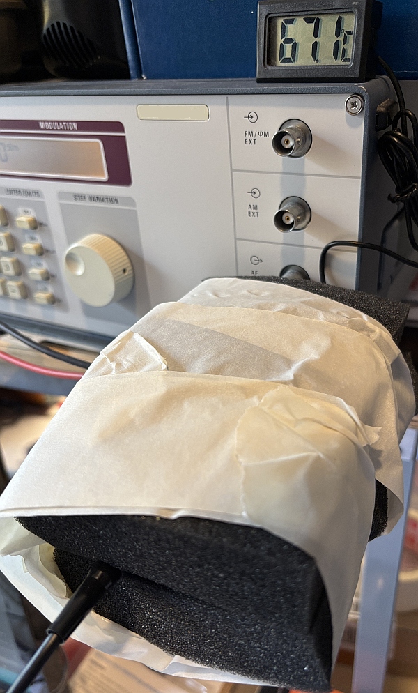
To prevent short circuits, I first wrapped a layer of parchment paper around the sensor. Then I wrapped the floral wire onto the parchment paper and secured the wire with heat-resistant Kapton tape, as shown in the following photo:
Additionally, I wrapped a temperature sensor for monitoring and soldered the floral wire to 4mm laboratory sockets so I could connect my laboratory power supply to it.
After some tinkering with the power supply’s output current and the resulting heating and cooling times, I decided to wrap the sensor in some foam. With a heating current of 4 amps, which results in a voltage drop of 4 volts across the heating wire, you get a heating power of 16 watts. This is enough to heat the sensor to 70 degrees Celsius and more, and to achieve a sufficiently slow cooling rate that you can assume that each measurement can be taken in approximate thermal equilibrium. You can do a cross-check by comparing the heating curve with the cooling curve. If both produce approximately the same results, then this assumption is justified.
The following diagrams show the results of the measurements. The temperature was measured with the internal AD7415 temperature sensor, with is in close proximity to the RF diode.
I decided to measure at levels of -40 dBm, -20 dBm, -10 dBm, 0 dBm, and 10 dBm, at temperatures ranging from approximately room temperature to over 70 degrees Celsius. The measurement curves marked with an upward arrow were measured during heating. The downward arrow indicates measurements during cooling of the sensor:
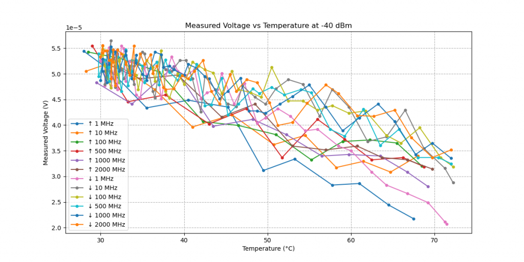
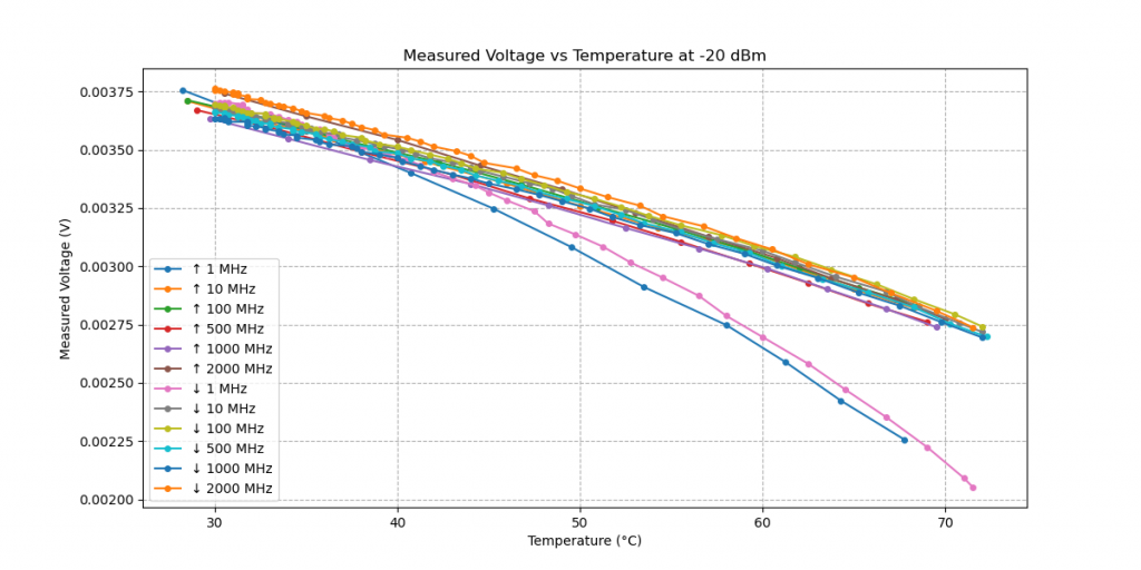
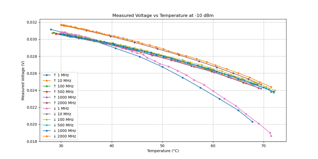
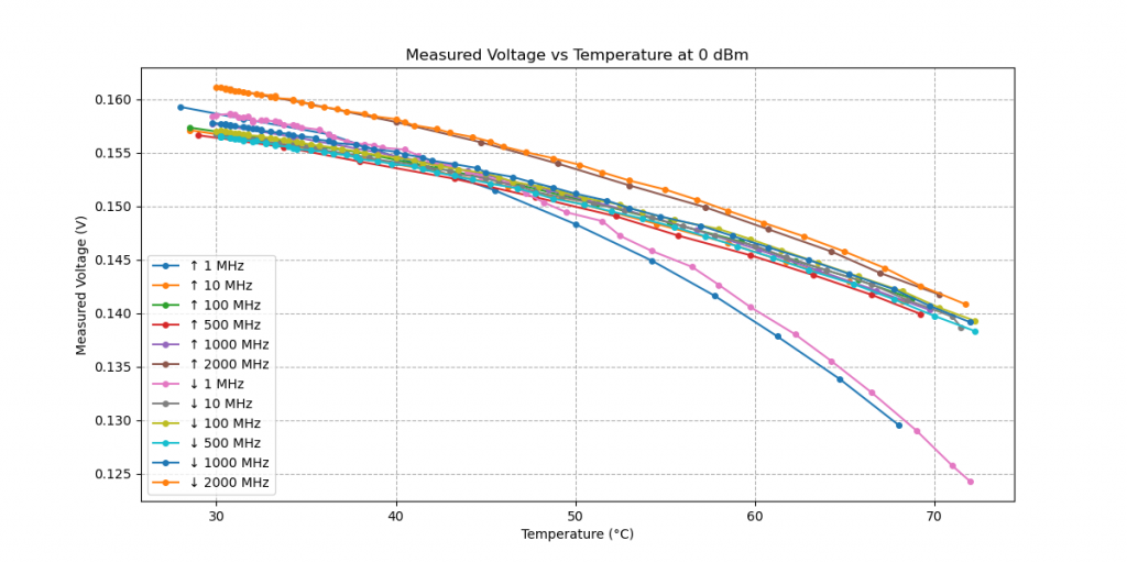
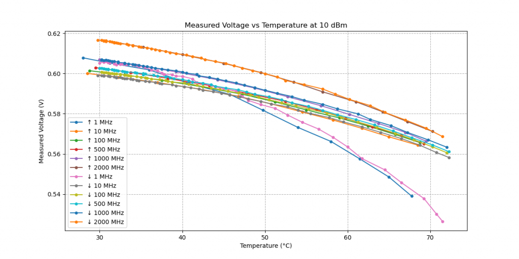
The measurements at the lowest frequency of 1 MHz are striking. Here, it appears that the coupling capacitor(s), which determine the lower frequency limit of the detector, or rather their temperature dependence, are more important than the temperature-dependent properties of the RF diode rectifier.
Maybe I should do some more measurements at low frequencies?