
The old MCU ran directly from the USB Bus voltage, namely ~4.75…5V.
All the peripherals had to be connected to the same voltage, because this was also the I/O voltage of the MCU.
Now the situation is different: The Raspberry Pico runs on 3.3V and has an I/O voltage of 3.3V.
Was the Pico a bad choice then? Should I have better taken an Arduino Nano with an I/O voltage of 5V?
No; as it turns out, almost all the ICs in the RF power sensor work also well on 3.3V. All but one: The reference voltage source ADR431 needs a minimum of 4.5 Volts in order to work properly.
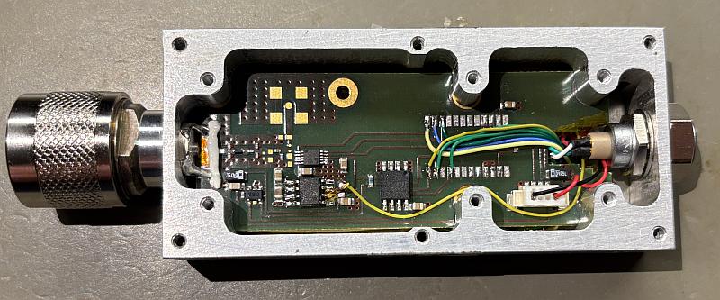
In order to solve this problem, I desoldered the ADR431, glued a small piece of Kapton on the power supply pad 2 of the ADR431 and soldered the ADR431 in again. I then took a separate piece of wire and connected pin 2 to VBUS.
All the other power supply pins, the ADC, EEPROM and the temperature sensor, are connected to the same power supply net, which is connected to the 3.3V output of the Pico.
The underside of the device now looks like this:
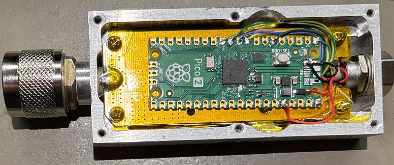
And here is the top side:
The connections between the peripherals and the old MCU are shown here:
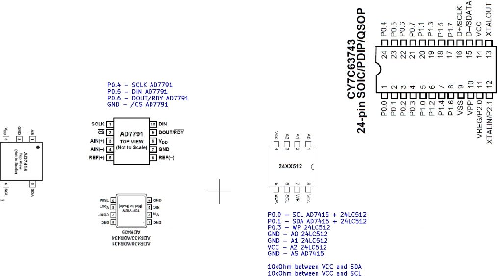
and this diagram shows the connections to the Pico:

The I²C address of the temperature sensor AD7415 is 73 (dec).
The I²C address of the 25LC512 is 84 (dec).
I have read out the EEPROM with the Pico and tried to make sense of the calibration data but I gave up very soon.
Apparently, I’ll have to do the calibration myself.
But next, I’ll probably need drivers for the ADC and the temperature sensor…