
The ADC AD7791 is the most important part of the RF power sensor – apart from the diode detector. It has to convert the output voltage of the diode detector accurately and with very low fluctuations into digital values.
At low input powers, the input voltages become very low:
-60 dBm at 50 Ohms is equal to 0.22mVrms or 0.31mVpk
-50 dBm at 50 Ohms is equal to 0.7mVrms or 1mVpk
-40 dBm at 50 Ohms is equal to 2.2mVrms or 3.1mVpk
and the diode detector will put out only a fraction of this voltages to the ADC.
In addition to low noise conversion, the input current of the ADC should also be very low in order to present a very low load to the diode detector.
Unfortunately, I could not find a Micropython driver for the AD7791. I then decided to write my own driver and to write it in such a way that all of the features of the AD7791 can be used later on, because I wasn’t sure how to use the ADC later: in single conversion mode or in continuous conversion mode? And at what sample rate?
It took a while to write and test the driver.
It can be found here: https://github.com/papamidas/RFpowersensor/tree/master/AD7791
The temperature sensor AD7415 is somewhat easier to understand and use than the AD7791: It uses I²C, which is a better defined interface than SPI. And it has fewer registers.
But I couldn’t find a Micropython driver for this part either and had to write my own.
It can be found here:
https://github.com/papamidas/RFpowersensor/tree/master/AD7415
In order to test the correct output of negative celsius temperatures, I put the detector together with the USB cable into the freezer over night. I then put everything in a cooler bag for shopping for frozen goods. A freezer plastic bag provided protection against condensation:
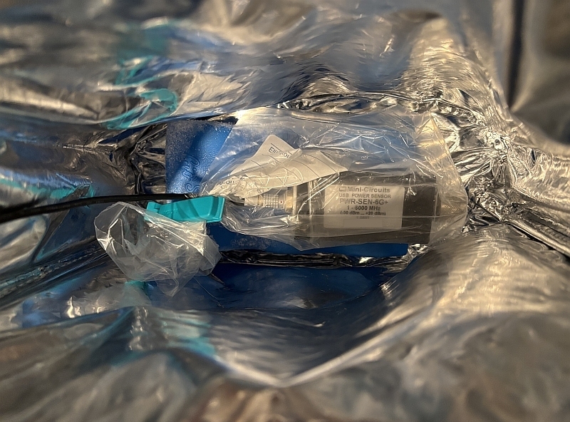
This way I could easily see that my driver correctly puts out also negative Celsius temperatures.
So far, so good…