
I was curious to find out how fast the interrupt response of a STM32H743 can be.
I connected a simple square wave generator to Pin PG3 of my old NUCLEOH743ZI-Board.
A PWM output of my raspberry Pi PICO was used as a square wave generator with a PWM frequency of 1234 Hz.
In addition, I connected a scope for watching the rising edge of this PWM signal to input channel 1 and PG2 to input channel 2
The Task
- Write a simple program that lets the STM32H743 react to a rising edge on PG3 (=EXTI3)
- The ISR should do nothing more than setting PG2 high as fast as possible and then again setting it back to low as fast as possible
I used STM32CUBEIDE v1.12.1 for this, setting the CPU clock speed to 400 MHz. Anything else was left at default values.
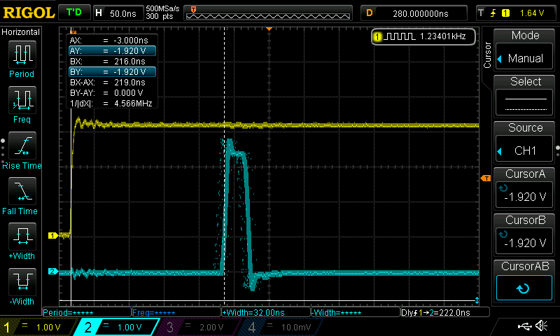
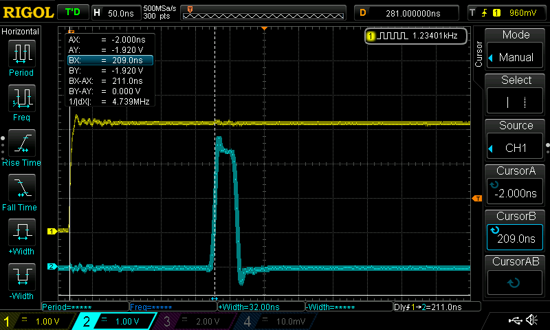
The results were astounding and disappointing:
It took 380 ns between the rising edge of my interrupt generating signal and the rising edge of PG2.
And it took another 266 ns to the falling edge of PG2:
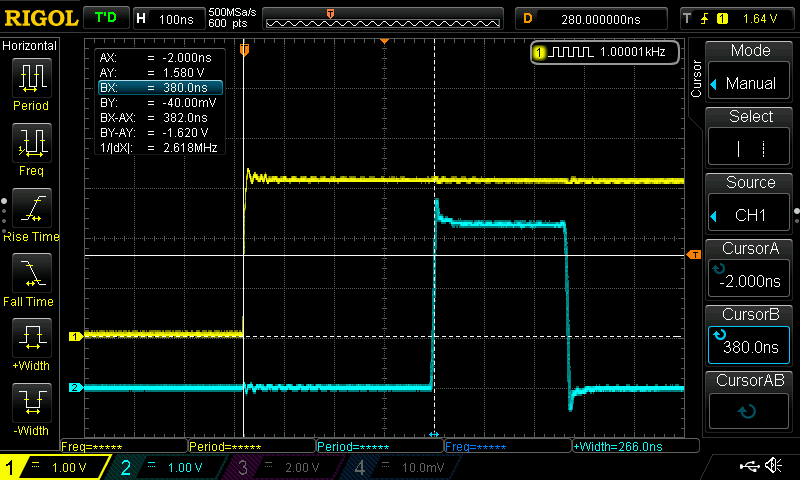
This is much slower than I expected!
Here is the code of the interrupt function, located in main.c:
/* USER CODE BEGIN 4 */
void HAL_GPIO_EXTI_Callback(uint16_t GPIO_Pin)
{
    HAL_GPIO_WritePin(GPIOG, GPIO_PIN_2, GPIO_PIN_SET);
    HAL_GPIO_WritePin(GPIOG, GPIO_PIN_2, GPIO_PIN_RESET);
}

/* USER CODE END 4 */
And this is what the compiler makes of it (.list-File):
08000640 <HAL_GPIO_EXTI_Callback>:

/* USER CODE BEGIN 4 */
void HAL_GPIO_EXTI_Callback(uint16_t GPIO_Pin)
{
 8000640:	b580      	push	{r7, lr}
 8000642:	b082      	sub	sp, #8
 8000644:	af00      	add	r7, sp, #0
 8000646:	4603      	mov	r3, r0
 8000648:	80fb      	strh	r3, [r7, #6]
    HAL_GPIO_WritePin(GPIOG, GPIO_PIN_2, GPIO_PIN_SET);
 800064a:	2201      	movs	r2, #1
 800064c:	2104      	movs	r1, #4
 800064e:	4806      	ldr	r0, [pc, #24]	; (8000668 <HAL_GPIO_EXTI_Callback+0x28>)
 8000650:	f000 fc6e 	bl	8000f30 <HAL_GPIO_WritePin>
    HAL_GPIO_WritePin(GPIOG, GPIO_PIN_2, GPIO_PIN_RESET);
 8000654:	2200      	movs	r2, #0
 8000656:	2104      	movs	r1, #4
 8000658:	4803      	ldr	r0, [pc, #12]	; (8000668 <HAL_GPIO_EXTI_Callback+0x28>)
 800065a:	f000 fc69 	bl	8000f30 <HAL_GPIO_WritePin>
}
 800065e:	bf00      	nop
 8000660:	3708      	adds	r7, #8
 8000662:	46bd      	mov	sp, r7
 8000664:	bd80      	pop	{r7, pc}
 8000666:	bf00      	nop
 8000668:	58021800 	.word	0x58021800
.
.
.
08000f30 <HAL_GPIO_WritePin>:
  *            @arg GPIO_PIN_RESET: to clear the port pin
  *            @arg GPIO_PIN_SET: to set the port pin
  * @retval None
  */
void HAL_GPIO_WritePin(GPIO_TypeDef *GPIOx, uint16_t GPIO_Pin, GPIO_PinState PinState)
{
 8000f30:	b480      	push	{r7}
 8000f32:	b083      	sub	sp, #12
 8000f34:	af00      	add	r7, sp, #0
 8000f36:	6078      	str	r0, [r7, #4]
 8000f38:	460b      	mov	r3, r1
 8000f3a:	807b      	strh	r3, [r7, #2]
 8000f3c:	4613      	mov	r3, r2
 8000f3e:	707b      	strb	r3, [r7, #1]
  /* Check the parameters */
  assert_param(IS_GPIO_PIN(GPIO_Pin));
  assert_param(IS_GPIO_PIN_ACTION(PinState));

  if (PinState != GPIO_PIN_RESET)
 8000f40:	787b      	ldrb	r3, [r7, #1]
 8000f42:	2b00      	cmp	r3, #0
 8000f44:	d003      	beq.n	8000f4e <HAL_GPIO_WritePin+0x1e>
  {
    GPIOx->BSRR = GPIO_Pin;
 8000f46:	887a      	ldrh	r2, [r7, #2]
 8000f48:	687b      	ldr	r3, [r7, #4]
 8000f4a:	619a      	str	r2, [r3, #24]
  }
  else
  {
    GPIOx->BSRR = (uint32_t)GPIO_Pin << GPIO_NUMBER;
  }
}
 8000f4c:	e003      	b.n	8000f56 <HAL_GPIO_WritePin+0x26>
    GPIOx->BSRR = (uint32_t)GPIO_Pin << GPIO_NUMBER;
 8000f4e:	887b      	ldrh	r3, [r7, #2]
 8000f50:	041a      	lsls	r2, r3, #16
 8000f52:	687b      	ldr	r3, [r7, #4]
 8000f54:	619a      	str	r2, [r3, #24]
}
 8000f56:	bf00      	nop
 8000f58:	370c      	adds	r7, #12
 8000f5a:	46bd      	mov	sp, r7
 8000f5c:	f85d 7b04 	ldr.w	r7, [sp], #4
 8000f60:	4770      	bx	lr
.
.
.
In addition, the function HAL_GPIO_EXTI_Callback(uint16_t GPIO_Pin) is not directly the interrupt handler, it is rather a function that is called by HAL_GPIO_EXTI_IRQHandler(uint16_t GPIO_Pin):
08000f62 <HAL_GPIO_EXTI_IRQHandler>:
  * @brief  Handle EXTI interrupt request.
  * @param  GPIO_Pin: Specifies the port pin connected to corresponding EXTI line.
  * @retval None
  */
void HAL_GPIO_EXTI_IRQHandler(uint16_t GPIO_Pin)
{
 8000f62:	b580      	push	{r7, lr}
 8000f64:	b082      	sub	sp, #8
 8000f66:	af00      	add	r7, sp, #0
 8000f68:	4603      	mov	r3, r0
 8000f6a:	80fb      	strh	r3, [r7, #6]
    __HAL_GPIO_EXTID2_CLEAR_IT(GPIO_Pin);
    HAL_GPIO_EXTI_Callback(GPIO_Pin);
  }
#else
  /* EXTI line interrupt detected */
  if (__HAL_GPIO_EXTI_GET_IT(GPIO_Pin) != 0x00U)
 8000f6c:	f04f 43b0 	mov.w	r3, #1476395008	; 0x58000000
 8000f70:	f8d3 2088 	ldr.w	r2, [r3, #136]	; 0x88
 8000f74:	88fb      	ldrh	r3, [r7, #6]
 8000f76:	4013      	ands	r3, r2
 8000f78:	2b00      	cmp	r3, #0
 8000f7a:	d008      	beq.n	8000f8e <HAL_GPIO_EXTI_IRQHandler+0x2c>
  {
    __HAL_GPIO_EXTI_CLEAR_IT(GPIO_Pin);
 8000f7c:	f04f 42b0 	mov.w	r2, #1476395008	; 0x58000000
 8000f80:	88fb      	ldrh	r3, [r7, #6]
 8000f82:	f8c2 3088 	str.w	r3, [r2, #136]	; 0x88
    HAL_GPIO_EXTI_Callback(GPIO_Pin);
 8000f86:	88fb      	ldrh	r3, [r7, #6]
 8000f88:	4618      	mov	r0, r3
 8000f8a:	f7ff fb59 	bl	8000640 <HAL_GPIO_EXTI_Callback>
  }
#endif
}
 8000f8e:	bf00      	nop
 8000f90:	3708      	adds	r7, #8
 8000f92:	46bd      	mov	sp, r7
 8000f94:	bd80      	pop	{r7, pc}
	...
And not even this one is the actual interrupt handler! The actual interrupt handler function is this one:
08000700 <EXTI3_IRQHandler>:

/**
  * @brief This function handles EXTI line3 interrupt.
  */
void EXTI3_IRQHandler(void)
{
 8000700:	b580      	push	{r7, lr}
 8000702:	af00      	add	r7, sp, #0
  /* USER CODE BEGIN EXTI3_IRQn 0 */

  /* USER CODE END EXTI3_IRQn 0 */
  HAL_GPIO_EXTI_IRQHandler(GPIO_PIN_3);
 8000704:	2008      	movs	r0, #8
 8000706:	f000 fc2c 	bl	8000f62 <HAL_GPIO_EXTI_IRQHandler>
  /* USER CODE BEGIN EXTI3_IRQn 1 */

  /* USER CODE END EXTI3_IRQn 1 */
}
 800070a:	bf00      	nop
 800070c:	bd80      	pop	{r7, pc}
	...
Improvement #1: using bit-set-and-reset-registers BSRR for setting the GPIO output values
Yes, I know, this will hardly change the interrupt latency, but the 248 ns pulse width annoyed me the most.
Here is what I changed:
/* USER CODE BEGIN 4 */
void HAL_GPIO_EXTI_Callback(uint16_t GPIO_Pin)
{
    GPIOG->BSRR = (1 << 2);
    GPIOG->BSRR = (1 << 2) << 16;
}

/* USER CODE END 4 */
This compiles to:
/* USER CODE BEGIN 4 */
void HAL_GPIO_EXTI_Callback(uint16_t GPIO_Pin)
{
 8000640:	b480      	push	{r7}
 8000642:	b083      	sub	sp, #12
 8000644:	af00      	add	r7, sp, #0
 8000646:	4603      	mov	r3, r0
 8000648:	80fb      	strh	r3, [r7, #6]
    GPIOG->BSRR = (1 << 2);
 800064a:	4b06      	ldr	r3, [pc, #24]	; (8000664 <HAL_GPIO_EXTI_Callback+0x24>)
 800064c:	2204      	movs	r2, #4
 800064e:	619a      	str	r2, [r3, #24]
    GPIOG->BSRR = (1 << 2) << 16;
 8000650:	4b04      	ldr	r3, [pc, #16]	; (8000664 <HAL_GPIO_EXTI_Callback+0x24>)
 8000652:	f44f 2280 	mov.w	r2, #262144	; 0x40000
 8000656:	619a      	str	r2, [r3, #24]
}
 8000658:	bf00      	nop
 800065a:	370c      	adds	r7, #12
 800065c:	46bd      	mov	sp, r7
 800065e:	f85d 7b04 	ldr.w	r7, [sp], #4
 8000662:	4770      	bx	lr
 8000664:	58021800 	.word	0x58021800
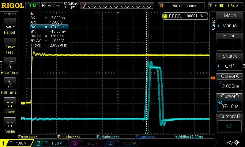
That looks much better!
The time between the rising edge of the interrupt signal PG3 and the rising edge of PG2 has improved only slightly (I measured a very jittery value of 374/384 ns), but the ON-time of PG2 has improved significantly: I measured 42 ns:
By the way:
Why not using Bit-banding?
Because the M7 family does not support this!
https://community.arm.com/support-forums/f/architectures-and-processors-forum/10266/why-cortex-m7-doesn-t-support-bit-banding
Improvement #2: putting the code directly into the ISR
This requires editing the file „stm32h7xx_it.c“:
void EXTI3_IRQHandler(void)
{
  /* USER CODE BEGIN EXTI3_IRQn 0 */
  if (__HAL_GPIO_EXTI_GET_IT(GPIO_PIN_3) != 0x00U)
  {
      __HAL_GPIO_EXTI_CLEAR_IT(GPIO_PIN_3);
      GPIOG->BSRR = (1 << 2);
      GPIOG->BSRR = (1 << 2) << 16;
  }
  return;
  /* USER CODE END EXTI3_IRQn 0 */
  HAL_GPIO_EXTI_IRQHandler(GPIO_PIN_3);
  /* USER CODE BEGIN EXTI3_IRQn 1 */

  /* USER CODE END EXTI3_IRQn 1 */
}
This compiles to:
080006d4 <EXTI3_IRQHandler>:

/**
  * @brief This function handles EXTI line3 interrupt.
  */
void EXTI3_IRQHandler(void)
{
 80006d4:	b480      	push	{r7}
 80006d6:	af00      	add	r7, sp, #0
  /* USER CODE BEGIN EXTI3_IRQn 0 */
  if (__HAL_GPIO_EXTI_GET_IT(GPIO_PIN_3) != 0x00U)
 80006d8:	f04f 43b0 	mov.w	r3, #1476395008	; 0x58000000
 80006dc:	f8d3 3088 	ldr.w	r3, [r3, #136]	; 0x88
 80006e0:	f003 0308 	and.w	r3, r3, #8
 80006e4:	2b00      	cmp	r3, #0
 80006e6:	d00b      	beq.n	8000700 <EXTI3_IRQHandler+0x2c>
  {
      __HAL_GPIO_EXTI_CLEAR_IT(GPIO_PIN_3);
 80006e8:	f04f 43b0 	mov.w	r3, #1476395008	; 0x58000000
 80006ec:	2208      	movs	r2, #8
 80006ee:	f8c3 2088 	str.w	r2, [r3, #136]	; 0x88
      GPIOG->BSRR = (1 << 2);
 80006f2:	4b06      	ldr	r3, [pc, #24]	; (800070c <EXTI3_IRQHandler+0x38>)
 80006f4:	2204      	movs	r2, #4
 80006f6:	619a      	str	r2, [r3, #24]
      GPIOG->BSRR = (1 << 2) << 16;
 80006f8:	4b04      	ldr	r3, [pc, #16]	; (800070c <EXTI3_IRQHandler+0x38>)
 80006fa:	f44f 2280 	mov.w	r2, #262144	; 0x40000
 80006fe:	619a      	str	r2, [r3, #24]
  }
  return;
 8000700:	bf00      	nop
  /* USER CODE END EXTI3_IRQn 0 */
  HAL_GPIO_EXTI_IRQHandler(GPIO_PIN_3);
  /* USER CODE BEGIN EXTI3_IRQn 1 */

  /* USER CODE END EXTI3_IRQn 1 */
}
 8000702:	46bd      	mov	sp, r7
 8000704:	f85d 7b04 	ldr.w	r7, [sp], #4
 8000708:	4770      	bx	lr
 800070a:	bf00      	nop
 800070c:	58021800 	.word	0x58021800
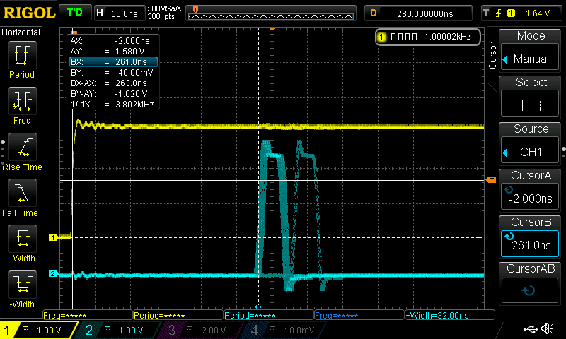
The time between the rising edge of the stimulus signal and rising edge has changed significantly: It varies now between 261 ns and 314 ns:
Improvement #3: Removing check of pending IT and lowering priority of other interrupts
EXTI3 is not a combined interrupt like EXTI(10…15). EXTI3 has its own interrupt vector, so it should be unneccessary to check EXTI_CPUPR1.
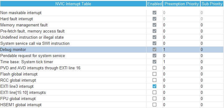
The interrupt priorities should be changed so that no other interrupt, at least during normal operation, interrupts the interrupt service routine for EXTI3.
The interrupt priorities were changed via CubeMX:
and here is the code of the ISR:
/**
  * @brief This function handles EXTI line3 interrupt.
  */
void EXTI3_IRQHandler(void)
{
  /* USER CODE BEGIN EXTI3_IRQn 0 */
      __HAL_GPIO_EXTI_CLEAR_IT(GPIO_PIN_3);
      GPIOG->BSRR = (1 << 2);
      GPIOG->BSRR = (1 << 2) << 16;
  return;
  /* USER CODE END EXTI3_IRQn 0 */
  HAL_GPIO_EXTI_IRQHandler(GPIO_PIN_3);
  /* USER CODE BEGIN EXTI3_IRQn 1 */

  /* USER CODE END EXTI3_IRQn 1 */
}
The code above compiles to:
080006dc <EXTI3_IRQHandler>:

/**
  * @brief This function handles EXTI line3 interrupt.
  */
void EXTI3_IRQHandler(void)
{
 80006dc:	b480      	push	{r7}
 80006de:	af00      	add	r7, sp, #0
  /* USER CODE BEGIN EXTI3_IRQn 0 */
      __HAL_GPIO_EXTI_CLEAR_IT(GPIO_PIN_3);
 80006e0:	f04f 43b0 	mov.w	r3, #1476395008	; 0x58000000
 80006e4:	2208      	movs	r2, #8
 80006e6:	f8c3 2088 	str.w	r2, [r3, #136]	; 0x88
      GPIOG->BSRR = (1 << 2);
 80006ea:	4b06      	ldr	r3, [pc, #24]	; (8000704 <EXTI3_IRQHandler+0x28>)
 80006ec:	2204      	movs	r2, #4
 80006ee:	619a      	str	r2, [r3, #24]
      GPIOG->BSRR = (1 << 2) << 16;
 80006f0:	4b04      	ldr	r3, [pc, #16]	; (8000704 <EXTI3_IRQHandler+0x28>)
 80006f2:	f44f 2280 	mov.w	r2, #262144	; 0x40000
 80006f6:	619a      	str	r2, [r3, #24]
  return;
 80006f8:	bf00      	nop
  /* USER CODE END EXTI3_IRQn 0 */
  HAL_GPIO_EXTI_IRQHandler(GPIO_PIN_3);
  /* USER CODE BEGIN EXTI3_IRQn 1 */

  /* USER CODE END EXTI3_IRQn 1 */
}
 80006fa:	46bd      	mov	sp, r7
 80006fc:	f85d 7b04 	ldr.w	r7, [sp], #4
 8000700:	4770      	bx	lr
 8000702:	bf00      	nop
 8000704:	58021800 	.word	0x58021800
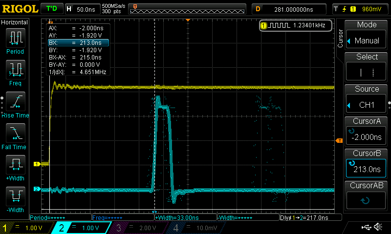
And this is the corresponding scope display:
What else can be done for improving the response?
„Improvement #4“: Clearing the Interrupt Bit later in the code
This was no improvement at all!
My idea was to call __HAL_GPIO_EXTI_CLEAR_IT(GPIO_PIN_3); after the output pulse on PG2.
And I decided to set and reset PG2 by using a few lines of assemly code, because I realized that the GCC compiler loads R3 twice with the same address without changing R3 in between, see code above.
This was the code:
/**
  * @brief This function handles EXTI line3 interrupt.
  */
void EXTI3_IRQHandler(void)
{
  /* USER CODE BEGIN EXTI3_IRQn 0 */
      __asm volatile ("ldr  r3, =0x58021800");
      __asm volatile ("mov	r2, #0x4");
      __asm volatile ("str	r2, [r3, #24]");
      __asm volatile ("mov	r2, #0x40000");
      __asm volatile ("str	r2, [r3, #24]");
      __HAL_GPIO_EXTI_CLEAR_IT(GPIO_PIN_3);
  return;
  /* USER CODE END EXTI3_IRQn 0 */
  HAL_GPIO_EXTI_IRQHandler(GPIO_PIN_3);
  /* USER CODE BEGIN EXTI3_IRQn 1 */

  /* USER CODE END EXTI3_IRQn 1 */
}
and here you can see what has happened:
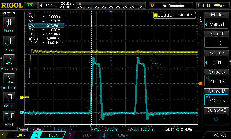
There are 2 output pulses!
How can this be?
It looks like clearing the interrupt bit in the interrupt pending register EXTI_CPUPR1 takes a long time and when the interrupt service routine has ended, the interrupt bit is still active and triggers another interrupt!
Meanwhile the pending bit has been cleared, so that after the second interrupt no more further interrupts are generated.
Is it possible to program some delay before the return statement in the ISR?
Yes, it is, but it takes a lot of NOP()s!
Look here:
/**
  * @brief This function handles EXTI line3 interrupt.
  */
void EXTI3_IRQHandler(void)
{
  /* USER CODE BEGIN EXTI3_IRQn 0 */
      __asm volatile ("ldr  r3, =0x58021800");
      __asm volatile ("mov	r2, #0x4");
      __asm volatile ("str	r2, [r3, #24]");
      __asm volatile ("mov	r2, #0x40000");
      __asm volatile ("str	r2, [r3, #24]");
      __HAL_GPIO_EXTI_CLEAR_IT(GPIO_PIN_3);
      __NOP();
      __NOP();
      __NOP();
      __NOP();
      __NOP();
      __NOP();
      __NOP();
      __NOP();
      __NOP();
      __NOP();
      __NOP();
      __NOP();
      __NOP();
      __NOP();
      __NOP();
      __NOP();
      __NOP();
      __NOP();
  return;
  /* USER CODE END EXTI3_IRQn 0 */
  HAL_GPIO_EXTI_IRQHandler(GPIO_PIN_3);
  /* USER CODE BEGIN EXTI3_IRQn 1 */

  /* USER CODE END EXTI3_IRQn 1 */
}
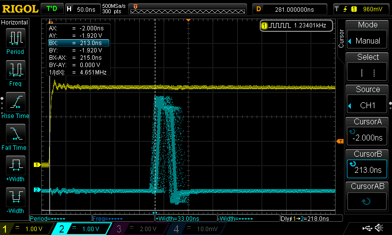
It requires inserting 18 NOP()s until the double pulses vanish:
But it still seems like they do not vanish completely…
This is a really strange behavior!
I decided to restore the order of execution:
void EXTI3_IRQHandler(void)
{
  /* USER CODE BEGIN EXTI3_IRQn 0 */
      __HAL_GPIO_EXTI_CLEAR_IT(GPIO_PIN_3);
      __asm volatile ("ldr  r3, =0x58021800");
      __asm volatile ("mov	r2, #0x4");
      __asm volatile ("str	r2, [r3, #24]");
      __asm volatile ("mov	r2, #0x40000");
      __asm volatile ("str	r2, [r3, #24]");
  return;
  /* USER CODE END EXTI3_IRQn 0 */
  HAL_GPIO_EXTI_IRQHandler(GPIO_PIN_3);
  /* USER CODE BEGIN EXTI3_IRQn 1 */

  /* USER CODE END EXTI3_IRQn 1 */
}
This seems to remove double pulses completely. The following screen shot was made after running the scope for several minutes in infinite persistance display mode:
Improvement #5: Using tightly coupled memories ITCM and DTCM
In order to use ITCM and DTCM memories, which run without any wait states even at 400 MHz, I made a copy of the linker script file STM32H743ZITX_RAM.ld and called it STM32H743ZITX_TCM.ld .
I then searched through the file and replaced every occurence of >RAM_EXEC by >ITCMRAM.
Then I changed the project settings in STM32CubeIDE via
Project -> Properties -> C/C++ Build -> Settings -> MCU GCC Linker -> General -> Linker Script from STM32H743ZITX_FLASH.ld to STM32H743ZITX_TCM.ld
Then I cleaned the project and built it again.
This it what comes out:
Result:
The shortest interrupt response time that I could observe between an externally applied interrupt signal and a GPIO output signal is about 210 ns.
What does that mean?
If I take into account an interrupt latency of 12 to 14 clock cycles of an ARM CORTEX-M7 core (see chapter 5.2 of this white paper) and another 8-16 clock cycles for clearing the pending ISR flag and setting the GPIO output, considering that accessing a peripheral address is way slower than accessing the ITCM, then everything sums up to about 30 clock cycles.
But my oscilloscope says that it takes 210 ns until something happens, which is 210 ns * 400 MHz = 84 clock cycles.
So where are the missing 54 clock cycles?
Are they all consumed by the EXTI?
I think so, I have no better explanation…
i am having exactly the same problem. stm32h725, 400 MHz sysclk, EXTI4 on PE4 interrupts. for testing the handler only clears the interrupt and toggles PE12.
i am coding in bare assembly, not using HAL at all. during init, i copy all code to ITCM at 0x00000000, including stripping the flash offsets from the vector table, then shift PC tomove execution to sram only. i set VTOR to 0 to map the system lookup of the vector table to the ITCM block. i am not using FPU and have explicitly turned off the bits for including FPU registers in the context frame.
i can see incremental improvements from each of the steps, both in reduced latency and reduced jitter, but the best i can do is 168 ns. this makes no sense to me at all. it should be 30 ns for stacking the frame, and 25 ns more to execute the handler code up to the GPIOBSRR line to change the output. since the gpio bus is 2x slower clocking, allow another 10ns max for those lines. there is over 100 ns stall somewhere that i can’t find.
did you learn anything more?
Hi,
Toggling a simple pin on the H7 is very slow as I remember it.
Try doing a simple endless loop, with all interrupts disabled, that just set and then clear an IO pin.
With a STM32F4 it’s extremely fast, with a H7 not so much. Could be part of the explanation.
Best regards