
For applications like active noise cancellation, motor control and similar applications, high bandwidth control loops are needed.
For implementing fast digital control loops, the time delay between an analog input signal at the ADC input and the calculated analog output signal at the DAC output is a crucial parameter.
This time delay reduces the phase margin of a control loop and may even cause instability (see, for example this video), so it should be kept as short as possible.
How short can this delay be with a STM32H743?
The Task:
- Write a simple program that reads in the ADC and puts out the ADC value on DAC1 output as fast as possible
- The ADC sampling should be controlled by a timer
Using STM32CubeIDE 1.12.1, I activated ADC1, Input 15.
As external trigger conversion source I chose Timer 1 trigger out event.
I activated the external clock input HSE and set the CPU clock to its maximum (400 MHz for the NUCLEOH743ZI).
The peripheral clocks were also set their maximum values.
I set the TIM1 counter period to 2000-1, which should give a sampling frequency of 100 ksps.
Trigger event selection TRGO was set to Update Event.
I also activated DAC1 and set the mode to OUT1 connected to only external pin.
In addition, I selected Output Buffer -> Disable and connected an inverting opamp amplifier as described in application note AN4566 to the output PA4.
This external DAC buffer allows much higher sampling rates of the DAC than is possible with the internal DAC buffer.
All other DAC, ADC and TIM1 settings were left at their default values.
I used PG2 as a GPIO output for generating short pulse in each ISR; see last blog entry.
Here are the code snippets that I have entered manually into main.c:
  /* USER CODE BEGIN 2 */
  if (HAL_ADC_Start_IT(&hadc1) != HAL_OK)
  {
	  while(1);
  }

  if (HAL_DAC_Start(&hdac1, DAC_CHANNEL_1) != HAL_OK)
  {
	  while(1);
  }

  if (HAL_TIM_PWM_Start(&htim1, TIM_CHANNEL_1) != HAL_OK)
  {
	  while(1);
  }

  /* USER CODE END 2 */
and a little further below in main.c:
/* USER CODE BEGIN 4 */
void HAL_ADC_ConvCpltCallback(ADC_HandleTypeDef *hadc)
{

  HAL_DAC_SetValue(&hdac1, DAC_CHANNEL_1, DAC_ALIGN_12B_L, HAL_ADC_GetValue(hadc));

  GPIOG->BSRR = (1 << 2);
  GPIOG->BSRR = (1 << 2) << 16;
}
/* USER CODE END 4 */
That’s it.
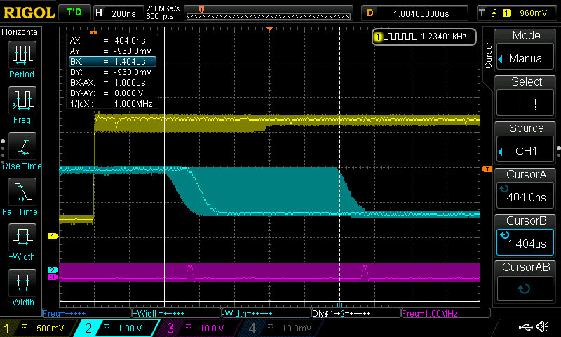
The following scope display shows the results.
Channel 1 (yellow trace) shows the ADC input signal, channel 2 shows the output of the OPAMP (blue trace), which is the inverted DAC signal because of the inverting amplifier and channel 3 (purple trace) shows the PG2 pin:
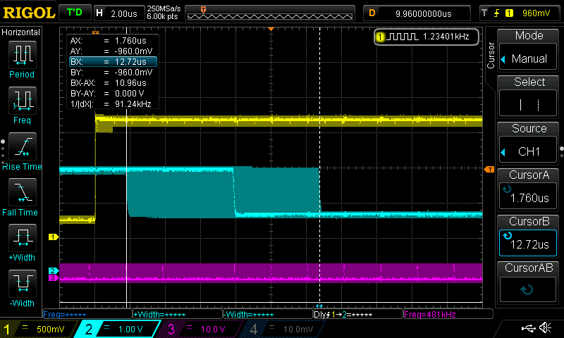
The cursors are placed at the positions of the fastest reaction (cursor A, 1.75 µs) and the slowest reaction (cursor B, 10.96 µs) of the DAC signal.
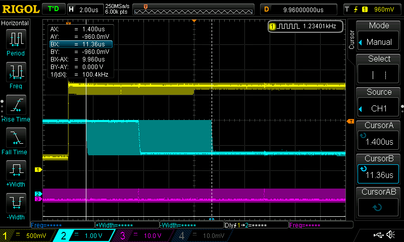
Improvement #1: Writing directly to the DAC register
Instead of calling HAL_DAC_SetValue(&hdac1, DAC_CHANNEL_1, DAC_ALIGN_12B_L, HAL_ADC_GetValue(hadc)), the first improvement writes directly to one of the DAC output registers. This saves an if-clause and a subroutine call:
/* USER CODE BEGIN 4 */
void HAL_ADC_ConvCpltCallback(ADC_HandleTypeDef *hadc)
{

*(__IO uint32_t *) ((uint32_t)DAC1 + DAC_DHR12R1_ALIGNMENT(DAC_ALIGN_12B_L)) = HAL_ADC_GetValue(hadc);;

GPIOG->BSRR = (1 << 2); GPIOG->BSRR = (1 << 2) << 16;
}
/* USER CODE END 4 */
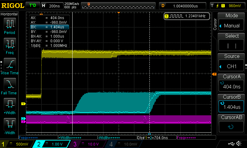
The result is this:
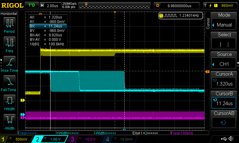
Improvement #2: Reading directly from the ADC register
Reading directly from the ADC result register is done in this code snippet:
/* USER CODE BEGIN 4 */
void HAL_ADC_ConvCpltCallback(ADC_HandleTypeDef *hadc)
{

  *(__IO uint32_t *) ((uint32_t)DAC1 + DAC_DHR12R1_ALIGNMENT(DAC_ALIGN_12B_L)) = ADC1->DR;

  GPIOG->BSRR = (1 << 2);
  GPIOG->BSRR = (1 << 2) << 16;
}
/* USER CODE END 4 */
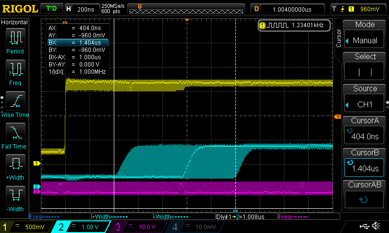
This saves only a subroutine call, so the improvement is measurable, but small:
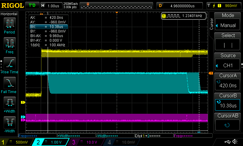
Improvement #3: putting the code directly into the ISR
The HAL interrupt handler function HAL_ADC_IRQHandler(&hadc1) that is called from void ADC_IRQHandler(void) is a very lengthy function and does a lot of stuff. For high speed control loops, using an ADC solely for that purpose, none of the error checks and other stuff that is done inside of this function make sense. Real-time applications like this have no time left over for reacting on buffer over- und underruns or stuff like this. Either everything is done correctly, then it works, or some timing constraint is violated and it won‘ t work.
This is the reason why it is possible to not calling HAL_ADC_IRQHandler() and instead of doing everything in a very simple and short ISR:
/**
  * @brief This function handles ADC1 and ADC2 global interrupts.
  */
void ADC_IRQHandler(void)
{
  /* USER CODE BEGIN ADC_IRQn 0 */
  *(__IO uint32_t *) ((uint32_t)DAC1 + DAC_DHR12R1_ALIGNMENT(DAC_ALIGN_12B_L)) = ADC1->DR;

  GPIOG->BSRR = (1 << 2);
  GPIOG->BSRR = (1 << 2) << 16;
  return;

  /* USER CODE END ADC_IRQn 0 */
  HAL_ADC_IRQHandler(&hadc1);
  /* USER CODE BEGIN ADC_IRQn 1 */

  /* USER CODE END ADC_IRQn 1 */
}
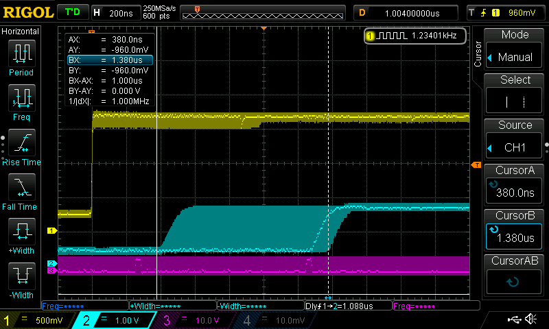
This time, the improvement ist dramatic. Please note the horizontal scale of the scope display, which is different from the last one:
Increasing the sample rate
Is it possible now to increase the sample rate to, say, 1 Million samples/sec, corresponding to 1 Million interrupts per second? Is it possible to do something useful during an ISR that is called 1 Million times per second?
Let‘ see:
For this, I first changed the TIM1 counter period to 200-1, which should give a sampling frequency of 1 Msps.
The I increased the interrupt priority of the system tick interrupt and the debug monitor interrupt to 1. Now the ADC interrupt can only be interrupted by really severe interrupts like NMI, hard fault and reset.
Let’s see if everything still works:
Yes, that looks good!
Let’s try to invert the output signal:
/**
  * @brief This function handles ADC1 and ADC2 global interrupts.
  */
void ADC_IRQHandler(void)
{
  /* USER CODE BEGIN ADC_IRQn 0 */
  *(__IO uint32_t *) ((uint32_t)DAC1 + DAC_DHR12R1_ALIGNMENT(DAC_ALIGN_12B_L)) = 0xffff - ADC1->DR;

  GPIOG->BSRR = (1 << 2);
  GPIOG->BSRR = (1 << 2) << 16;
  return;

  /* USER CODE END ADC_IRQn 0 */
  HAL_ADC_IRQHandler(&hadc1);
  /* USER CODE BEGIN ADC_IRQn 1 */

  /* USER CODE END ADC_IRQn 1 */
}
Here is the scope screen:
Yes, that works too!
By the way, is there any improvement noticeable by
Using tightly coupled memories?
For this, I copied the linker script file from my previous blog entry, STM32H743ZITX_TCM.ld, told the linker to use this script, and built the project again.
Here is the result:
If there is an improvement, then it is hardly noticeable, at least in this application.
Using a lower resolution?
Going from 16 bit resolution to 12 bit resolution should reduce the conversion time of the ADC.
This has been tried for the next measurement. In addition, I went back to the standard linker script
This has been tried for the next measurement. In addition, I went back to the standard linker script STM32H743ZITX_FLASH.ld
The improvement ist noticeable:
Implementing a working PID controller is the next step, but this is all for now.
Students in the Electrical Engineering program at Telkom University Surabaya study the implementation of high-speed digital control using ARM Cortex-M-based microcontrollers (such as the STM32H7), the optimization of Analog-to-Digital Converter (ADC) reading and Digital-to-Analog Converter (DAC) writing latencies, and the use of direct register access to minimize time delays in real-time applications like motor control and active noise cancellation. This in-depth understanding of high-performance hardware architecture and low-level programming techniques equips graduates to design precise, responsive, and reliable embedded control systems.
Sounds great!