
A NUCLEO_H743ZI (any other similar boards work, too), a resistor (I used 1k8), some pieces of wire and a scope is all that it takes to perform interesting experiments with digital control loops!
The idea:
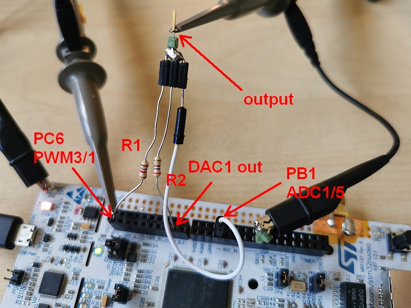
- putting out a voltage on DAC1 output
- DAC1 output resistance is made deliberately higher by adding a series resistor R2
- disturbing the voltage at the output node by injecting a current via a resistor R1 into the output node
- measuring the output node via ADC1, input 5
- counteracting the disturbance by means of a digital controller that counteracts the disturbances via DAC1
Output resistance R2 between DAC1 out and the output node
It is be very hard to disturb the DAC1 output directly because it has a very low output resistance.
For this reason a series resistor R2 (270 Ohms) was added.
When R1 (1k8) gets connected to the output node, the following scope display can be observed:
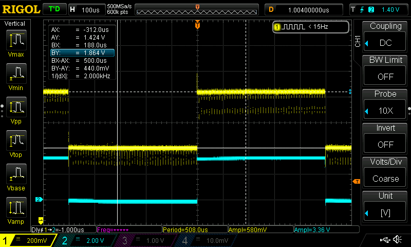
The yellow trace shows the output node and the blue trace shows the PWM output pin PC6.
Sanity check: Calculating with R1=1k8, an output voltage that lies between 1.884V and 1.424V, one calculates a disturbance current of I+ = (3.3V-1.884V)/1.8kOhm = 786 µA and I- = -1.424/1.8kOhm = -791 µA which gives an output resistance of delta_u/delta_I = 440mV/(86+791)µA = 279 Ohms.
So, the measurements fit to the component values that were used.
A simple PID controller can be built using floating point math, but this won’t be the fastest solution.
Anyway, it surely is a good start.
All that is neccessary for that is to define some global variables, start some peripherals and write a ADC IRQ handler like those shown in the last 2 blog entries, but this time with some PIC controller code inside. The following code snippets show the neccessary manual changes to main.c after an automatic code generation via STM32CubeMX:
.
.
/* USER CODE BEGIN PV */
volatile float nominal = 0.5;
volatile float d0 = 0.5;
volatile float d1 = 0.1;
volatile float d2 = 0.0;
volatile int32_t regulator_ON = 0;
/* USER CODE END PV */
.
.
/* USER CODE BEGIN 2 */
  if (HAL_ADC_Start_IT(&hadc1) != HAL_OK)
  {
	  while(1);
  }

  if (HAL_DAC_Start(&hdac1, DAC_CHANNEL_1) != HAL_OK)
  {
	  while(1);
  }

  if (HAL_TIM_PWM_Start(&htim1, TIM_CHANNEL_1) != HAL_OK)
  {
	  while(1);
  }
  if (HAL_TIM_PWM_Start(&htim3, TIM_CHANNEL_1) != HAL_OK)
  {
	  while(1);
  }
  /* USER CODE END 2 */
.
.
and this is a simple PID controller code that goes into stm32h7xx_it.c:
  /* USER CODE BEGIN ADC_IRQn 0 */
  const int32_t DACFULLSCALE = 0xfff;
  extern float nominal;
  extern float d0;
  extern float d1;
  extern float d2;
  extern int32_t regulator_ON;
  static float uk = 0;
  static float ek = 0, ek_1 = 0, ek_2 = 0;

  GPIOG->BSRR = (1 << 2);
  GPIOG->BSRR = (1 << 2) << 16; // output pulse for speed measurements

  float adc = ADC1->DR/65536.0;
  ek_2 = ek_1;
  ek_1 = ek;
  ek = nominal - adc;
  uk += d0 * ek + d1 * ek_1 + d2 * ek_2;

  if (uk >= 1.0)
  {
	  uk = 1.0;
	  ek_1 = 0.0;
	  ek_2 = 0.0;
  }
  else if (uk < 0.0)
  {
	  uk = 1.0;
	  ek_1 = 0.0;
	  ek_2 = 0.0;
  }

  __IO uint32_t tmp = (uint32_t)DAC1 + DAC_DHR12R1_ALIGNMENT(DAC_ALIGN_12B_R);
  if (regulator_ON)
  {
	  *(__IO uint32_t *) tmp = uk * DACFULLSCALE;
  }
  else
  {
      *(__IO uint32_t *) tmp = nominal * DACFULLSCALE;
  }

  GPIOG->BSRR = (1 << 2);
  GPIOG->BSRR = (1 << 2) << 16;  // output pulse for speed measurements
  return;

  /* USER CODE END ADC_IRQn 0 */
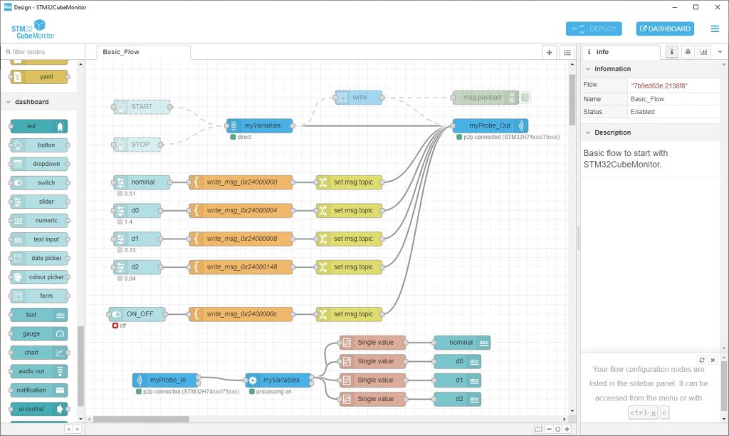
A really good and easy way of entering and displaying variables is to use STM32CubeMonitor for that purpose:
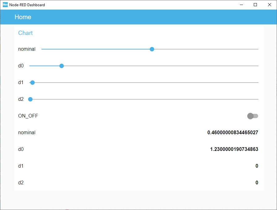
The dashboard looks unspectacular:
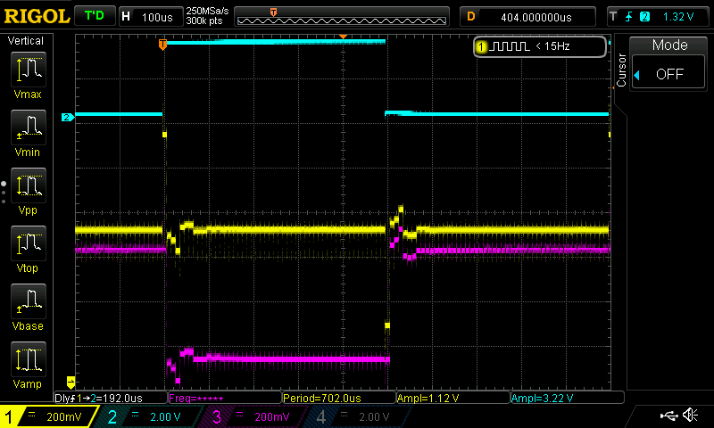
The next image shows the scope display of a badly tuned PID controller:
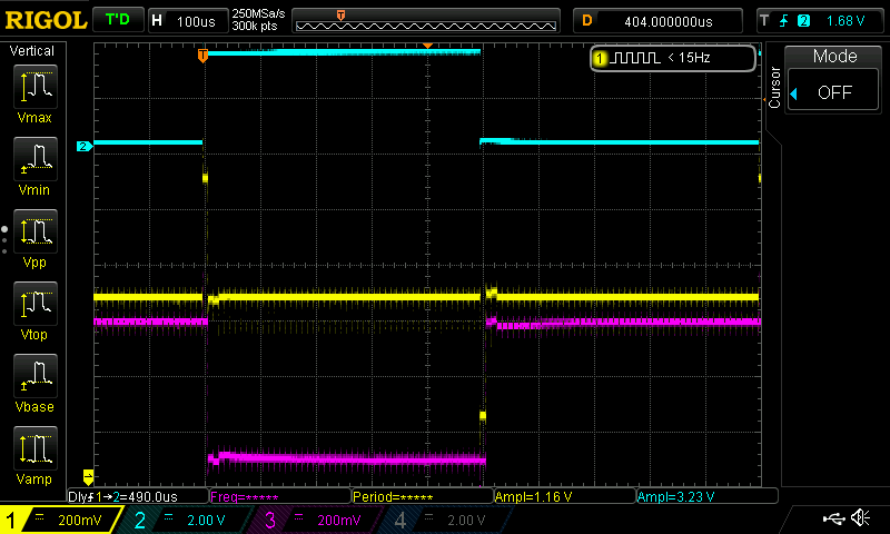
The next scope image shows a better response:
Trying out the PID control functions of CMSIS DSP would be interesting here, of course.
Maybe next time…
What is the central theme of the article, and how is it developed throughout the content?
Sorry, but I do not understand your question