
This new blog entry is about a USB RF power sensor.
I haven’t had much time for leisure projects in recent years, but in this case, I thought it would be a small project I could manage. Of course, it turned out to be much more complex than I expected, and it’s still not finished…
Let’s start:
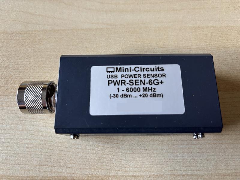
The power sensor Mini-Circuits PWR-SEN-6G+ (https://www.minicircuits.com/pdfs/PWR-6G+.pdf) was a nice device for measuring RF powers in a frequency range from 1 MHz up to 6GHz at power levels beginning at -30 dBm (1 Microwatts) up to +20 dBm (100 Milliwatts).
In contrast to earlier RF power sensors, it didn’t need a control unit, it didn’t even need a special power supply. It was an USB device, powered over USB. The device was sold together with a CD that contained software for a nice PC-GUI that displayed the power readings.
Unfortunately, Mini-Circuits used a proprietary protocol for communicating the power sensor data via USB to the PC.
The last operating system the PWR-SEN-6G+ worked with was the 32-bit Windows 7.
The PWR-SEN-6G+ stopped working with (64-bit-) Windows 10 and as far as I know, Mini-Circuits never released a Win10-version of their software.
Users who needed such a device and switched to Windows 10 had to buy a new generation of RF power sensors. The old ones probably ended up in some dark closet, if they didn’t end up in the trash.
I came across such a device and unscrewed it to see what was inside and whether there was anything I could do to make it usable again.
But first: Let’s shed some light on RF power sensors in general:
An RF power sensor is usually nothing more than a box with an RF-connector, a 50 Ohms termination resistor connected to it and a diode detector with some means of measuring the rectified DC voltage.
In the case of an USB RF power sensor, this DC voltage is measured by some ADC. The ADC data gets transferred to the connected PC, where it is displayed in correct units (dBm) via some user application software.
In order to compensate for the temperature dependence of the diode forward voltage, an RF power sensor often contains a temperature sensor.
A good and accurate power sensor needs to be calibrated, so that is displays the correct power at each frequency that is to be measured, independent from the environmental temperature.
By the way: This is one big limitation of power sensors: Simple devices like this can only measure the RF power of CW signals accurately. And you have to type-in first the frequency of the signal that you want to measure.
More elaborated RF power sensors can do more, see for example https://cdn.rohde-schwarz.com/ymkt/na/content/Instrument_Fundamentals_seminar_materials/5_Instrument_Fundamentals_-_Power_Sensor_Basics.pdf
The calibration data of a power sensor is different for each individuum, so I would also expect to find some kind of memory, and EEPROM or something, inside.
Teardown:
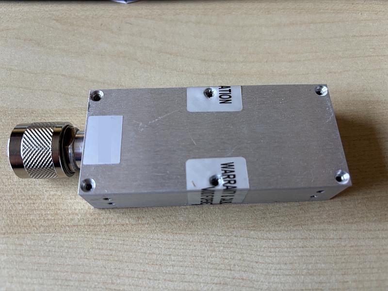
After removing the U-shaped outer plastic cover, the inner aluminum casing becomes visible. It has a top lid and a bottom lid. Each lid has 6 screws. The screws of the top lid are already removed in the picture:
After removing the top lid the top side of the PCB becomes visible:
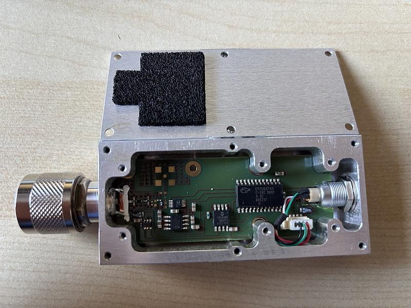
The top lid has some conducting foam glued to it, similar to the conducting foam that was used years ago for protecting integrating circuits against ESD charge buil-up between the pins.
The purpose of this foam here is most likely to reduce the Q-factor of the housing, and thus to reduce the effects of possible resonances at high frequencies? Maybe someone could comment on this? If this is true, what would the optimum thickness and conductivity of such a foam be? Has anyone experiences with such foams?
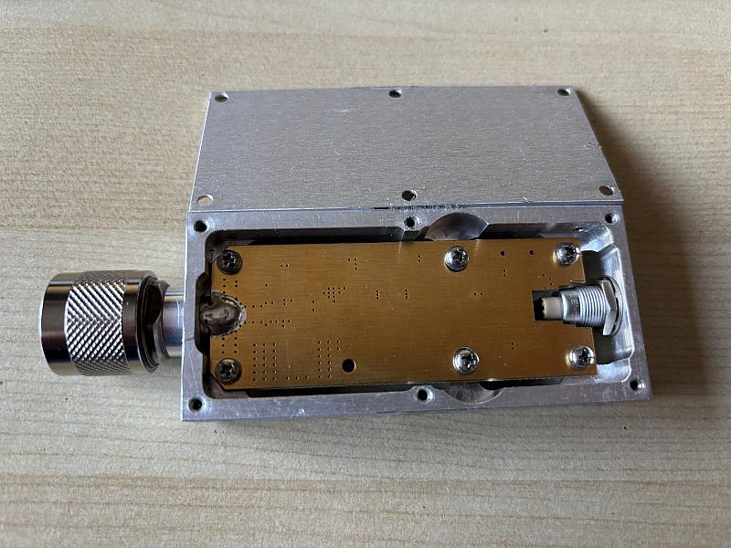
After removing the bottom lid, the bottom side of the PCB becomes visible:
to be continued…