
I do not have an RF power calibration source and I do not know where to borrow one.
What I have available is a used Rohde & Schwarz SMY02 signal generator, which I bought second-hand a few years ago and which has a calibration sticker from 2014. Unfortunately, this signal generator only goes up to 2.08 GHz, but I don’t have anything better.
I thought it might be useful to get an overview of the diode detector’s output voltage at different RF powers, frequencies, and temperatures to see how a calibration might work best.
I was able to borrow an RF power meter for a few hours to check the calibration of my SMY02 at a few selected points. Overall, the measured levels agreed with the output levels I had randomly set on the SMY02.
After that, it quickly became clear to me that a manual measurement would take far too long to get an overview of the diode detector’s behavior.
So I had to try an automatic measurement somehow.
The SMY02 has an IEEE488 interface on the back (also called an IEC625- or GPIB-interface) for performing such measurements.
Unfortunately, I don’t have an IEEE488-interface available.
I was therefore very happy to have found the AR488 project (https://github.com/Twilight-Logic/AR488), or rather its predecessor, which can be found here: https://egirland.blogspot.com/2014/03/arduino-uno-as-usb-to-gpib-controller.html
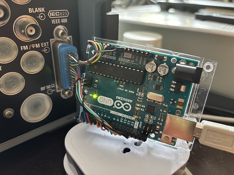
For this, I disassembled an ancient printer cable with a Centronics connector that I found in my basement. The Centronics connector didn’t have the right number of pins, but I was able to surgically remove and saw off the inner contact carrier so that it fit exactly into the 25-pin IEEE488 socket on the SMY02. Here is a picture of my home-built USB-to-IEEE488-Interface:
I also had to write a simple command-line-interface for my RF power sensor.
With the help of artificial intelligence, or rather with Github’s Copilot and VSCode, the CLI was written faster than I expected. The result can be found at https://github.com/papamidas/RFpowersensor/tree/master
Next, I wrote some rather sloppy code to scan the RF amplitudes and frequencies and read the diode detector readings.
The following code block shows what I did:
from ar488 import *
import pandas as pd
import sys

import subprocess
import re

def read_parameter_value(ser):
    # Read the prompt line
    prompt_line = ser.readline().decode().strip()
    # Read until newline (end of value line)
    response_line = ser.readline().decode().strip()
    # Parse the response: "PARAM_NAME value"
    try:
        param, value = response_line.split(' ', 1)
        value = float(value)
        return param, value
    except Exception as e:
        print(f"Error parsing response: {response_line}")
        return None, None


def init_ar488(gpib, address=28):
    print("port name: {}".format(gpib.ser.name))
    print("baudrate: {}".format(gpib.ser.baudrate))
    print("timeout: {}".format(gpib.ser.timeout))

    time.sleep(2)
    print("reading version from AR488:")
    print(">> " + gpib.query("++ver"))

    print("current GPIB address:")
    print(">> " + gpib.get_current_address())
    print("setting address to {} for SMY02".format(address))
    gpib.set_address(address)
    print("new GPIB address:")
    print(">> " + gpib.get_current_address())
    print("assert IFC to make AR488 the controller-in-charge")
    # this doesn't seem necessary, at least with only one controller
    gpib.write("++ifc")
    print("turn on auto 2 mode (auto-read after query)")
    gpib.write("++auto 2")
    print("verify auto mode: ")
    print(">> " + gpib.query("++auto"))
    return gpib

def init_smy02():
    # Initialize the SMY02 synthesizer
    gpib.write("*RST")
    time.sleep(1)
    idn = gpib.query("*IDN?")
    print("Connected to: {}".format(idn.strip()))
    return idn.strip()

def set_frequency(freq):
    # Send frequency to synthesizer via GPIB
    gpib.write("RF {}".format(freq))
    time.sleep(0.5)
    gpib.write("RF?")
    f = gpib.read().strip().split()
    return(f[1])

def set_level(level):
    # Send output level to synthesizer via GPIB
    gpib.write("LEV {}".format(level))
    time.sleep(0.5)
    gpib.write("LEV?")
    l = gpib.read().strip().split()
    return(l[1])

def measure_voltage(rfp):
    rfp.write(b"v\r")
    param, val = read_parameter_value(rfp)
    v = [param, val]
    #print("voltage measurement: {}".format(v))
    return(v[1])

def measure_temperature(rfp):
    rfp.write(b"t\r")
    param, val = read_parameter_value(rfp)
    t = [param, val]
    #print("temperature measurement: {}".format(t))
    return(t[1])


import serial
try:
    rport="COM11"
    rbaudrate=115200
    rtimeout=5
    rfp = serial.Serial(port=rport, baudrate=rbaudrate, timeout=rtimeout)
    print(rfp.name)
except:
    sys.exit("error opening serial port {}".format(rport))

import time

with AR488(port = "COM13", timeout=1) as gpib:
    init_ar488(gpib, address=28)
    init_smy02()

    input("press Enter to begin scan...")

    data=[]
    flist=[]
    fstep=1e6
    fact=1e6
    while(fact<=2080e6):
        flist.append(fact)
        fact += fstep

    for frequency in flist:
        act_freq = set_frequency(frequency)

        for level in range(-60, 20, 5):  # -60 dBm to 19 dBm inclusive
            act_level = set_level(level)
            voltage = measure_voltage(rfp)
            temp = measure_temperature(rfp)
            data.append({'Frequency': act_freq, 'Level_dBm': act_level, \
                         'Measured_Voltage': voltage, 'Temperature_C': temp})
            print("F={} Hz, L={} dBm, V={} V, T={} C".format(act_freq, act_level, voltage, temp))

    df = pd.DataFrame(data)
    df.to_csv("smy02_rf_power_scan.csv", index=False)
    print("data written to smy02_rf_power_scan.csv")
    print(df)
    print(df.describe())

    # Set output level to 0 dBm at end of scan
    gpib.write("LEV 0")
#close serial port
rfp.close()
Because both the original power detector and its successor require the input of the measurement frequency with a resolution of 1 MHz, I decided to perform a frequency scan with a resolution of 1 MHz.
I chose 1 MHz as the starting frequency and 2080 MHz as the end frequency, which is the highest frequency my signal generator can output.
For each frequency, I set measurements between -60 dBm and 15 dBm with a spacing of 5 dBm, resulting in 16 level measurements per frequency. This makes a total of 2080 x 16 = 33,280 measurements.
My SMY02 had to run all night for these measurements. I was seriously worried about whether the internal relays in my old signal generator, which you can hear clacking with every step, would hold up. But the next day, the measurement was complete, and my SMY02 was still working.
This morning, a 1.27 MB CSV file with the measurement results was on my hard drive, which I was naturally curious to see…