
The question that interested me was:
How strongly does the SNR of the ADC-peripheral of the H7 depend on the chosen clock source?
Unfortunately, neither the H7 datasheets nor application notes like AN5354 treat this topic. The FFT plot shown in figure 1 of AN5354 looks astonishingly good. Unfortunately, ST does not publish the code and the measurement setup that would make it possible to reproduce this measurement.
The whole topic of clocking the ADC is missing in this AN, so I had to make my own measurements.
According to the manual and to the clock configurator of STM32CubeIDE/CubeMX, one can choose between 3 different clock sources for the ADC:
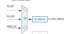
1. PLL2P
2. PLL3R
3. PER_CK
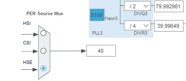
I was especially interested in using PER_CK, because the PER source MUX allows the choice between HSI, CSI and HSE as the clock source of this signal. I was interested in using HSE, which is the high-speed external clock signal that can be fed in to the PH0 pin of the MCU.
I modified the NUCLEO-H743ZI2 board in order to use an external clock oscillator as described in the previous blog entry. For this I used a 40 MHz SMD quartz oscillator (ABRACON ASAAIG-40.000MHZ-K-C-S-T) with a RMS phase jitter of < 1 ps (in a BW of 12 kHz…20MHz).
The idea was to drive the ADC by a low-noise clock that can go directly to the ADC without the detour via a PLL oscillator.
PLL oscillators can be sources of high phase noise unless they are designed especially for low-noise operation.
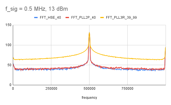
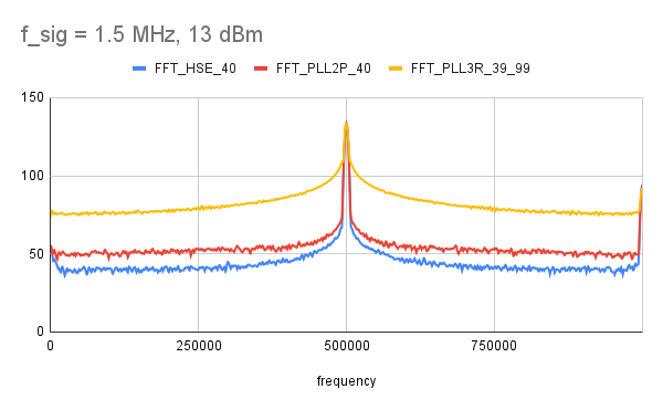
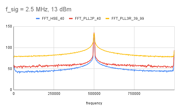
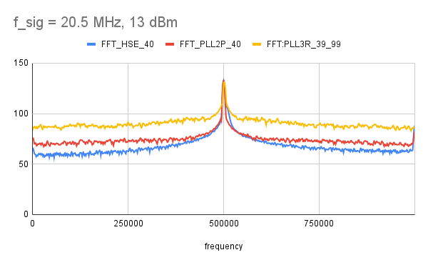
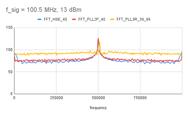
The following FFT plots show measurements at different signal frequencies with a signal power of 13 dBm and a balun transfomer like the one described in one of the older blog entries.
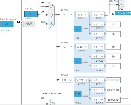
In order to choose between PLL2P, PLL3R and PER_CK, I used the graphical clock configurator of STM32CubeIDE/CubeMX.
For PPL2P, I used purely integer dividers, i.e. DIVM2=3, DIVN2=12 and DIVP2=4 and FRACN2=0, so that the output frequency of PLL2P would be the same as the input frequency, namely 40 MHz.
For PLL3R I decided to switch on fractional divider FRACN3 in order to see if it makes any difference to use a PLL with fractional dividers. This, of course, means to choose a slightly different PLL output frequency. With a setting of DIVM3=32, DIVN3=127, DIVP3=2 and FRACN3=8100 the ADC clock frequency should be 39.99649 MHz. The deviation of this clock frequency should be high enough in order to be seen at least at the higher input signal frequencies, but low enough in order to disturb the plots of the lower frequencies.
The following crops from the clock tree for the PLL3R version should illustrate this:
The generated code for the different clock selections can be found in the file stm32h7xx_hal_msp.c. The following table shows the different code lines that are generated for the different clock sources:
| ADC clocked by HSE | ADC clocked by PLL2P | ADC clocked PLL2R, fractional mode |
| void HAL_ADC_MspInit(ADC_HandleTypeDef* hadc) { … /** Initializes the peripherals clock */ PeriphClkInitStruct.PeriphClockSelection = RCC_PERIPHCLK_ADC; PeriphClkInitStruct.AdcClockSelection = RCC_ADCCLKSOURCE_CLKP; if (HAL_RCCEx_PeriphCLKConfig(&PeriphClkInitStruct) != HAL_OK) { Error_Handler(); } … | void HAL_ADC_MspInit(ADC_HandleTypeDef* hadc) { … /** Initializes the peripherals clock */ PeriphClkInitStruct.PeriphClockSelection = RCC_PERIPHCLK_ADC; PeriphClkInitStruct.PLL2.PLL2M = 3; PeriphClkInitStruct.PLL2.PLL2N = 12; PeriphClkInitStruct.PLL2.PLL2P = 4; PeriphClkInitStruct.PLL2.PLL2Q = 2; PeriphClkInitStruct.PLL2.PLL2R = 2; PeriphClkInitStruct.PLL2.PLL2RGE = RCC_PLL2VCIRANGE_3; PeriphClkInitStruct.PLL2.PLL2VCOSEL = RCC_PLL2VCOMEDIUM; PeriphClkInitStruct.PLL2.PLL2FRACN = 0.0; PeriphClkInitStruct.AdcClockSelection = RCC_ADCCLKSOURCE_PLL2; if (HAL_RCCEx_PeriphCLKConfig(&PeriphClkInitStruct) != HAL_OK) { Error_Handler(); } … | void HAL_ADC_MspInit(ADC_HandleTypeDef* hadc) { … /** Initializes the peripherals clock*/ PeriphClkInitStruct.PeriphClockSelection = RCC_PERIPHCLK_ADC; PeriphClkInitStruct.PLL3.PLL3M = 32; PeriphClkInitStruct.PLL3.PLL3N = 127; PeriphClkInitStruct.PLL3.PLL3P = 2; PeriphClkInitStruct.PLL3.PLL3Q = 2; PeriphClkInitStruct.PLL3.PLL3R = 4; PeriphClkInitStruct.PLL3.PLL3RGE = RCC_PLL3VCIRANGE_0; PeriphClkInitStruct.PLL3.PLL3VCOSEL = RCC_PLL3VCOMEDIUM; PeriphClkInitStruct.PLL3.PLL3FRACN = 8100.0; PeriphClkInitStruct.AdcClockSelection = RCC_ADCCLKSOURCE_PLL3; if (HAL_RCCEx_PeriphCLKConfig(&PeriphClkInitStruct) != HAL_OK) { Error_Handler(); } … |
In order to write the FFT data into Excel files, I modified the python script of https://github.com/papamidas/H7ADCBW
and added the following few lines:
...
import pandas as pd
...
        if keyboard.is_pressed("s"):
           filename = input("save to filename:")
           print("saving data to file --->", filename)
           specHeader = ["frequency","amplitude"]
           specDataArr = np.stack((freqs.T, YdB.T), axis=-1)
           dfspec = pd.DataFrame(specDataArr, columns=specHeader)
           timeHeader = ["ADCval"]
           dftime = pd.DataFrame(adc_frame, columns=timeHeader)
           with pd.ExcelWriter(filename + '.xlsx') as writer:
               dfspec.to_excel(writer, sheet_name='Spectrum')
               dftime.to_excel(writer, sheet_name='ADCFrame')
Input Frequency 0.5 MHz:
Input Frequency 1.5 MHz:
Input Frequency 2.5 MHz:
Input Frequency 20.5 MHz:
Input Frequency 100.5 MHz:
What conclusions are drawn in the article, and how do they relate to the broader context of the topic?
???