
I wanted to try out one of the newer NUCLEO-H743ZI2 boards, because they are populated with MCUs with the newer mask revision V.
In mask revision V, ST changed the clocking scheme of the ADC.
This new clocking scheme is interesting and I wanted to try out clocking the ADC by the H7 system clock instead of clocking the ADC via a PLL output. This is not possible with the older H7-MCU (mask revision Y) on board of the NUCLEO-H743ZI. The results of my measurements of the ADC driven by different clock sources will be discussed in a future blog entry.
The ZI2 is also equipped with the newer version V3 of the ST-LINK debugger.
But after experimenting a little with the ZI2, I found out that the MCU clock frequency shows some instabilities.
Then I found out that the H7 of the ZI2 is no more clocked from a stable 8-MHz-signal like it was on the ZI!
But first back to the ZI:
On the ZI-Board, the STM32H7 gets clocked via a stable 8-MHz-signal coming from the STM32F103 that is used for the on-board ST-LINK V2.
The STM32F103 is clocked by a 8-MHz-Quartz. This clock signal is made available on PA8/MCO of the STM32F103 for use by the STM32H7 as external clock signal.
On the ZI2, the situation is different:
On the ZI2, a much more powerful STM32F723 is used for the ST-LINK debugger. This new ST-LINK is called V3.
The STM32F723 is clocked by a 25 MHz clock-oscillator.
This choice was not very clever in my opinion. A much better choice would have been 24 MHz or 32 MHz.
But for the default configuration, this frequency does not play any role.
What does ST do here?
ST chose to put out 8 MHz on PA8/MCO of the STM32F723, most likely in order to stay compatible with the clock frequency on the ZI board.
But this 8-MHz signal is now derived from the internal, factory-trimmed 16-MHz-RC-oscillator of the F723 and not anymore from a precise quartz crystal, like it was done on the old ZI-board!
This RC oscillator is neither as precise as a quartz oscillator nor as stable and quite noisy. One cannot use this signal for precise timers or for interfaces that require a precise timing, like the CAN bus!
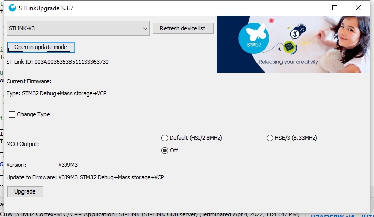
This is probably the reason why ST chose to offer an alternative clock signal that can be selected by starting a ST-LINK firmware upgrade. In the dialog window of this software you can change the clock signal from 8 MHz, driven by HSI, to 8.3333 MHz, driven by the external clock generator divided by three:
Now you have the choice between the devil and the deep blue sea:
Either you choose the imprecise, unstable and noisy HSI/2 = 8 MHz, which allows you to quickly find solutions for your clock tree in STM32CubeIDE by pressing the „resolve clock issues“ button
OR
you choose the precise, stable, low-noise HSE/3 = 8.3333333 MHz, which is a frequency that is impossible to type-in, and where the clock-issue-resolver never finds any solutions
In order to circumvent these problems, I decided to solder-in my own clock source instead of clocking the H7 by the ST-LINK V3.
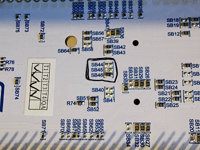
First I removed SB45, which connects the MCO-pin of the F723 to the PH0-OSC_IN-pin of the H7.
You can either remove it completely or you can move it over to position SB46. I chose the latter option.
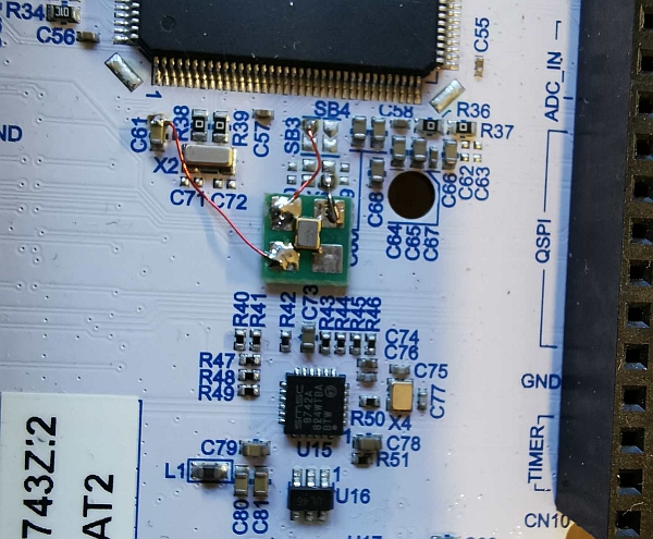
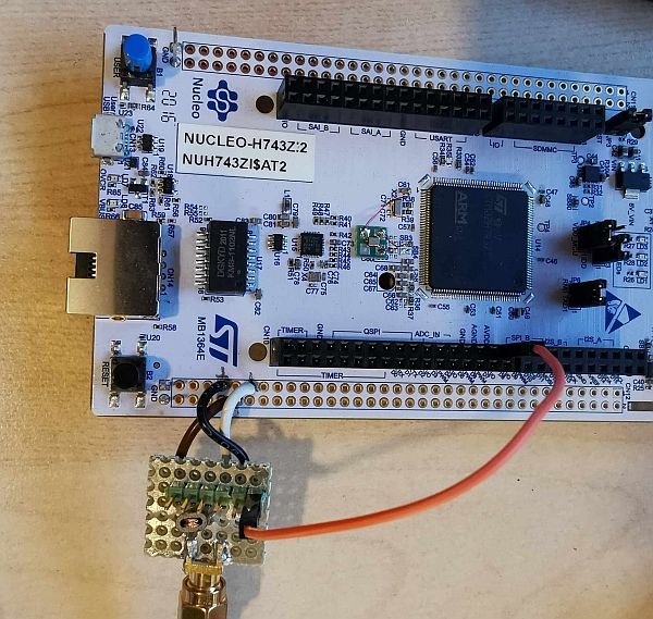
Then I soldered a 40-MHz-quartz-oscillator (I chose an ABRACON ASAAIG-40.000MHZ-K-C-S-T) to a small piece of PCB with 4 solder pads and glued this PCB onto the ZI2 board. I used some enameled wires for connecting the oscillator VCC, GND and OUT pads to the ZI2:
Then I built another input coupling transformer like the one described in my older blog entry. Now I was ready for my measurements:
2 Replies to “NUCLEO-H743ZI vs. NUCLEO-H743ZI2 and STLINK V3 vs. STLINK V2”