
continued from part I:
As explained in part I, the first version of my H7-SDR uses only one CIC filter of the DSFDM for filtering the I-signal and another one for filtering the Q-signal.
However, the DSFDM contains 4 filters (see chapter 30 of RM0433 Rev 7), so the two yet unused filters could probably be used for cascading with the two other filters.
I want to reduce the sample rate from the original 6070/2.25 ksps = 2697,777 ksps down to the range of 20 ksps, which is a convenient data rate for AM demodulation with an audio bandwidth of typically ~3 kHz, as will be shown later.
The CIC filter in my first version has a downsampling factor of 128, so the IQ sample rate is 21076.388 samples per second.
The DFSDM places some restrictions on the decimation factor and on the order of the filter, because the internal number of digits of the filter stages is limited to 32 bits. ST provides an Excel worksheet for calculating the internal resolution and bit length and gives overflow warnings when the limits are exceeded. See AN4990 for instructions on how to obtain this Excel sheet.
This limited number of 32 bits means that, for example, the order of the filter will be limited to 2 when choosing a decimation factor of 128.
Cascading two filters/decimators means that the first filter/decimator reduces the sample rate by a factor of X and the second filter reduces the then already reduced sample rate by another factor of Y, so that the total decimation factor is X*Y.
The decimation factors X and Y can be chosen such that higher filter orders become possible.
The next diagram shows what I mean: each I- and Q-mixer is now followed by two decimating filters instead of one:
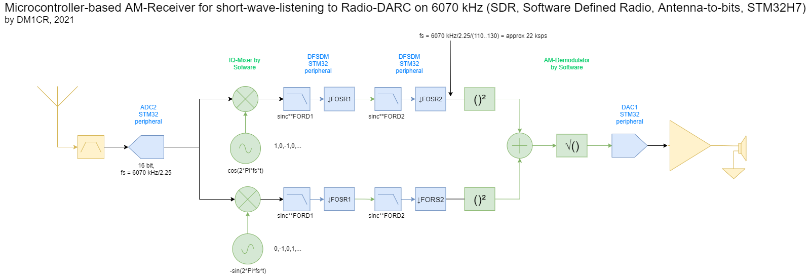
This gives raise to the question of which one of the many, many possibilities for choosing X and Y (that is, FOSR1, FORD1, FOSR2 and FORD2) is the best one?
In order to find answers to this question, I wrote a Python script for calculating the filter transfer functions. The script uses only floating point calculations, so the effects of a limited bit resolution cannot be seen. However, the results should be accurate enough to give a hint on how to choose the right filter arrangement and filter parameters.
The Python script with the name cic_xx_yy_filter_and_comp.py can be downloaded from here.
The first arrangement comprises 2 filters with a decimation factor of 11 and an order of 4. In order to make a comparison with the first version, the transfer function of the single filter (sinc**2, decimation by 128) can be seen as the blue curve.
The orange curve shows the transfer function of the first CIC filter and the green curve schows the transfer function of the second CIC filter. Both filters are sinc**4-filters with a decimation factor of 11. The total decimation factor is 11*11=121. The red curve shows the combined transfer function of both filters. The suppression of unwanted signals is much better than that of the single sinc**2-filter with a decimation factor of 128. According to ST’s Excel worksheet, these filters should be realizable on a STM32H7 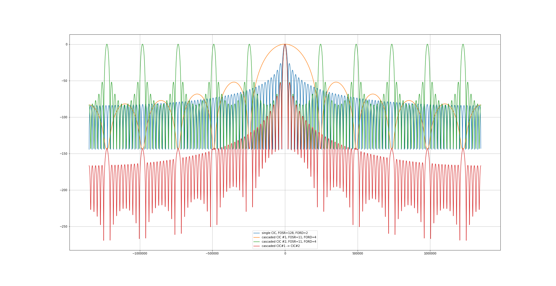
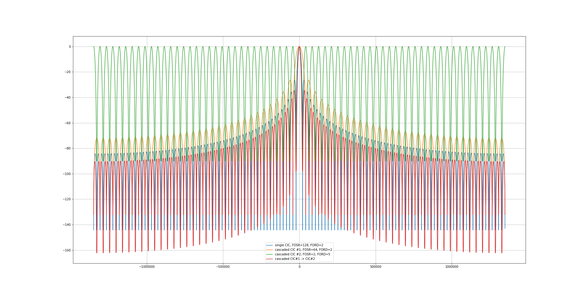
The next filters shows two extremes:
First comes a filter combination with sinc**2 and a decimation factor of 64 followed by a sinc**5-filter with a decimation factor of 2:
Compare this to a filter combination where the first and second filters are swapped: 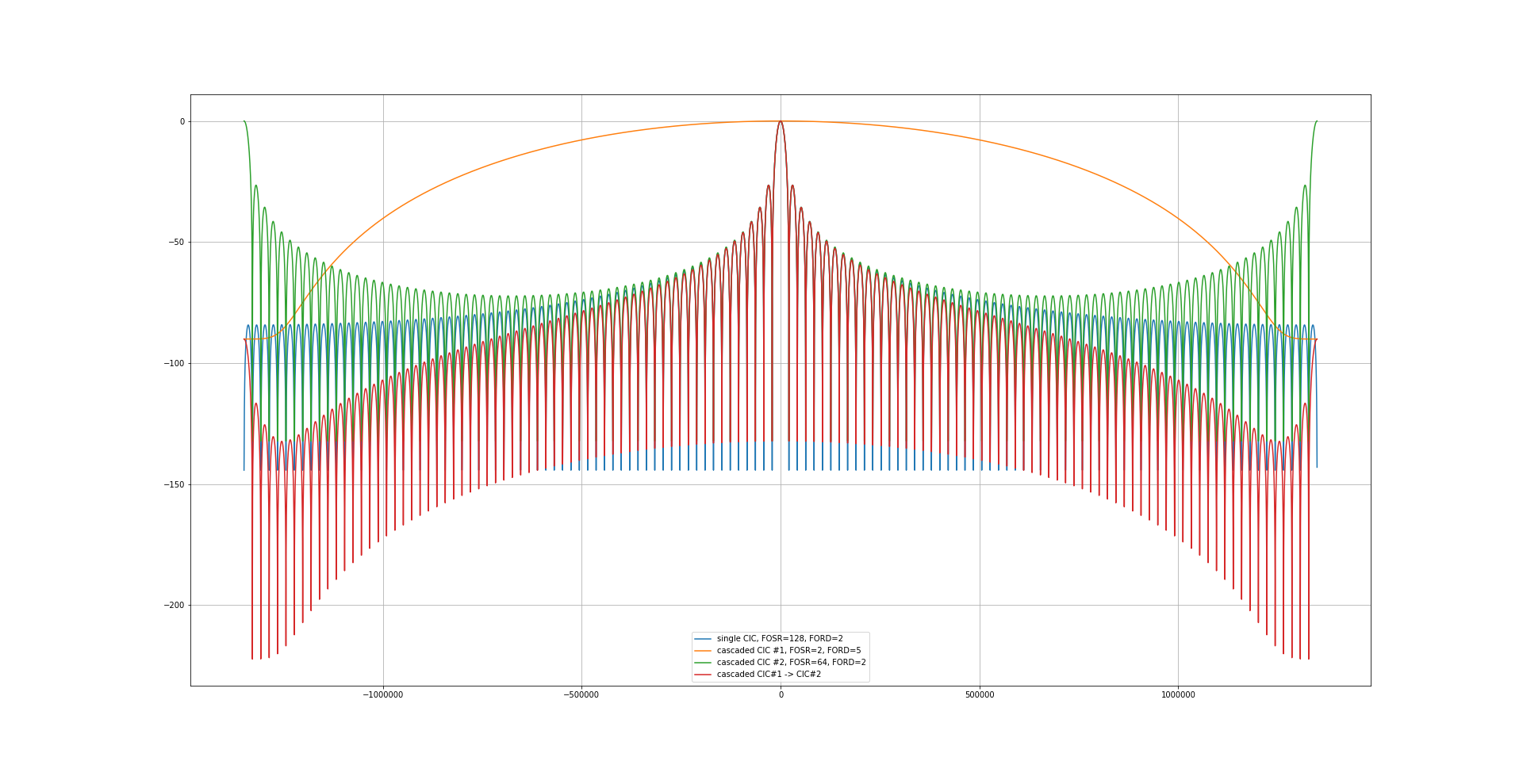
Neither combination is better than the first one!
The next filter is a combination of a sinc**5-filter with a decimation factor of 8 followed by a sinc**4-filter with a decimation factor of 15, giving a total decimation factor of 120:
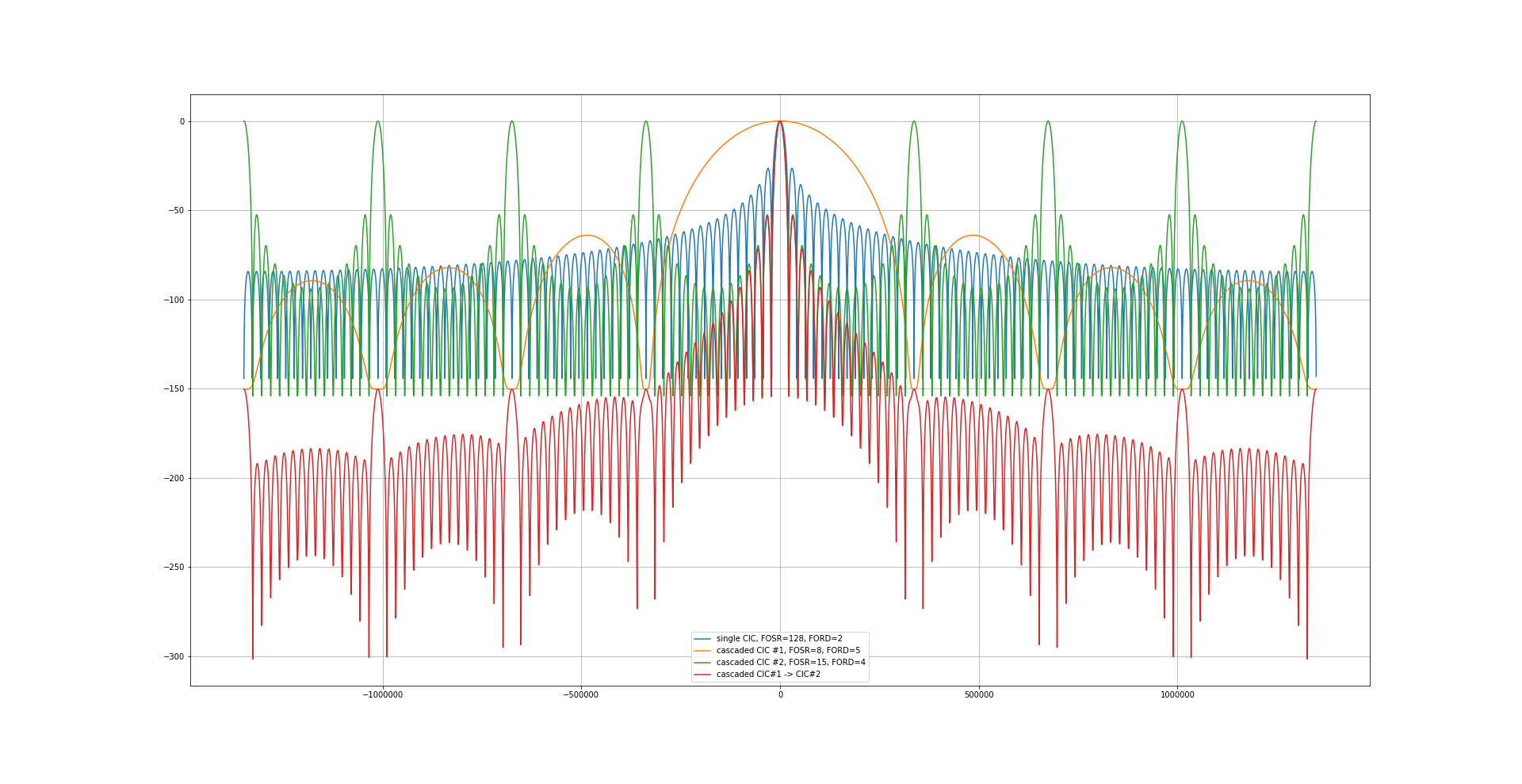
The last one is not so bad, but what about the swapped version?
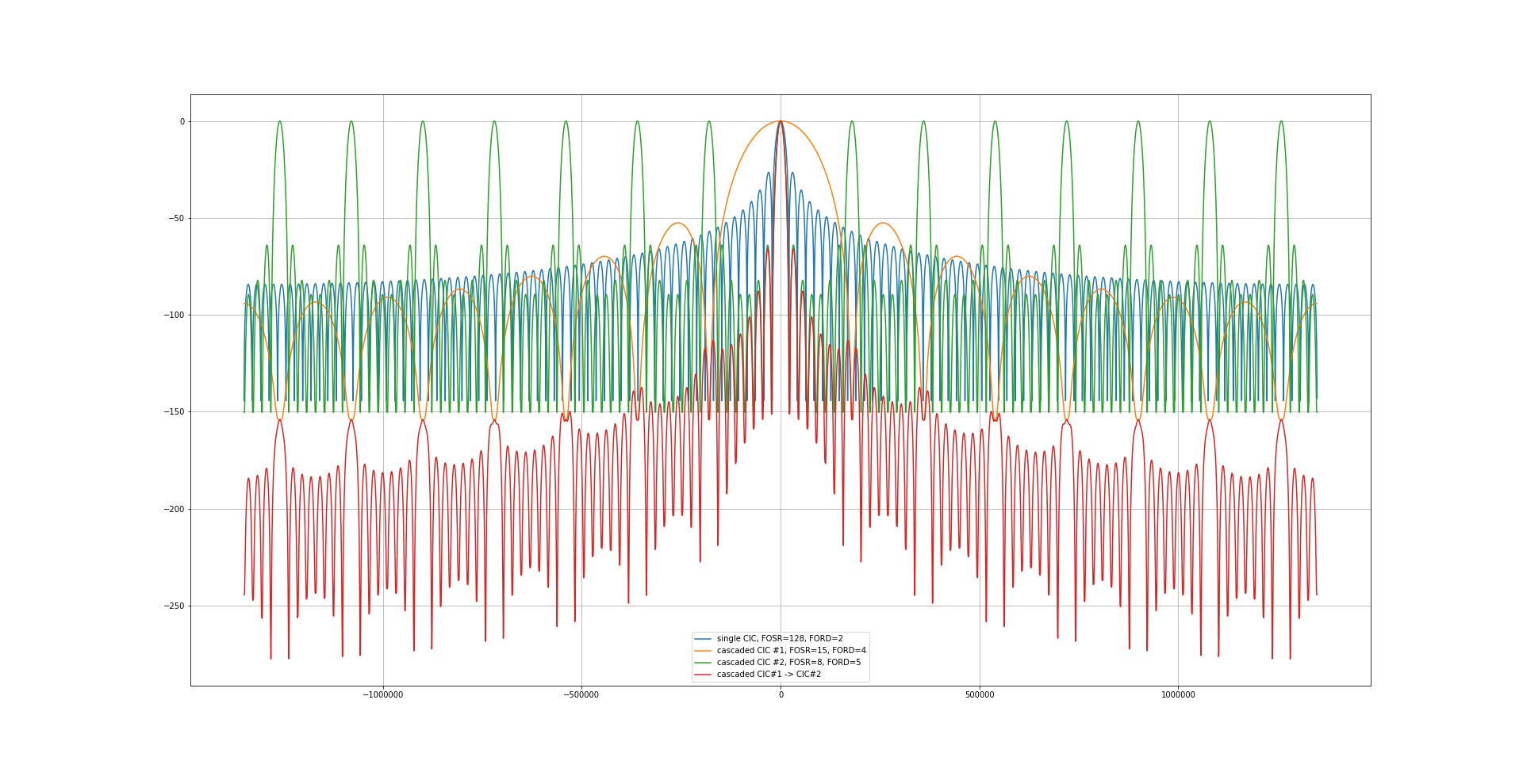
Now that looks really good! The highest unwanted signal is already more than 65 dB down, as can be seen on this zoomed plot:
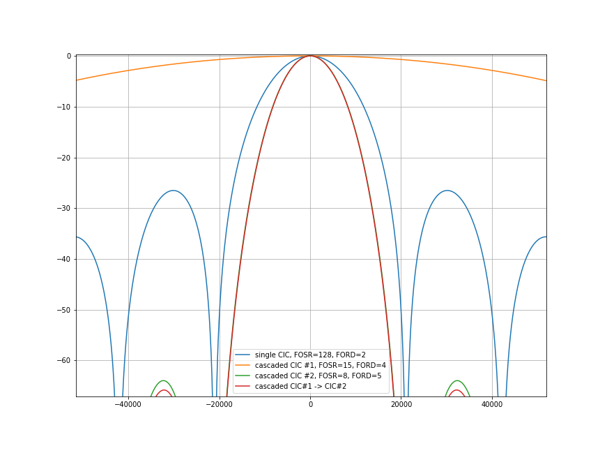
Filter combinations with a higher (but not too high) decimation factor in the first filter and a lower decimation factor in the second filter seem to be better than swapped filters.
This raises the question if a sinc**3-filter with a decimation factor of 17 followed by a sinc**4-filter with decimation factor of 7 (total decimation factor 17*7 = 119) is even better than the 15/sinc**4->8/sinc**5-combination?
The answer is NO, as can be seen from this diagram: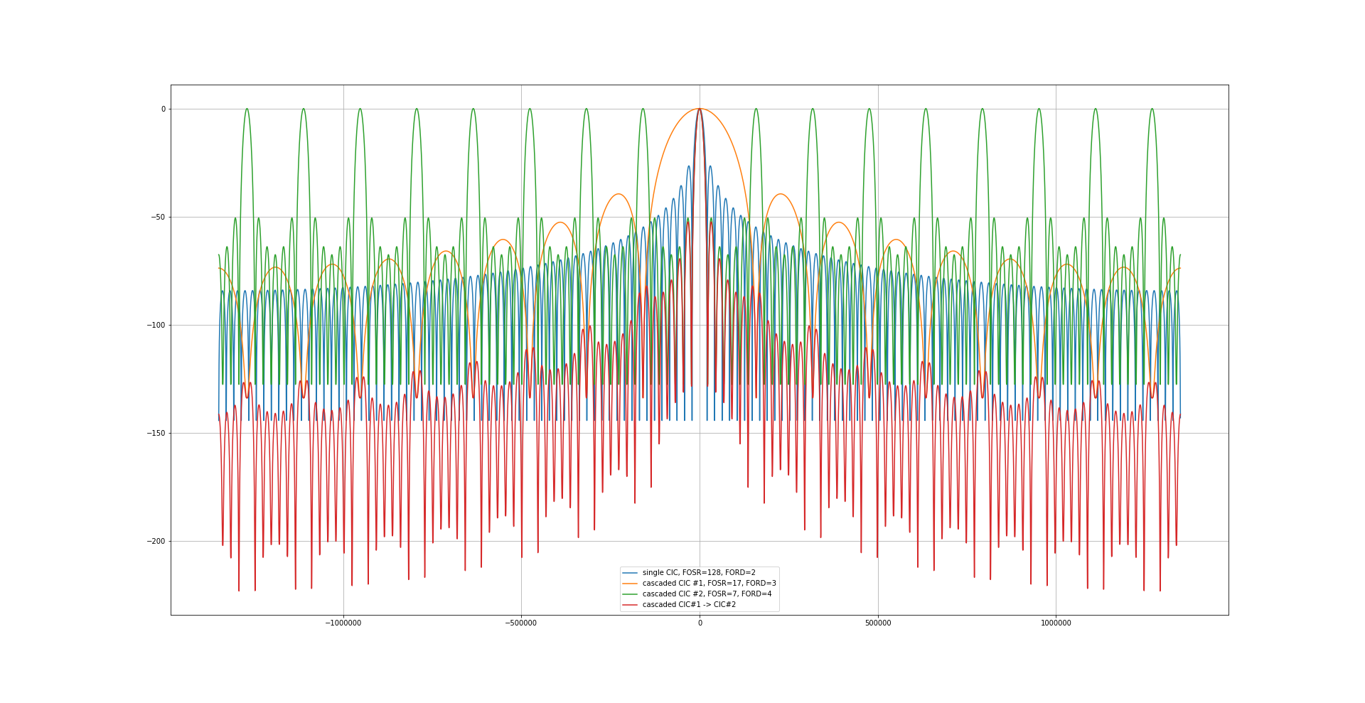
Conclusion:
The best filter combination seems to be a sinc**4-filter with a decimation factor of 15 followed by a sinc**5-filter with a decimation factor of 8.
This gives a total decimation factor of 15*8 = 120.
I think I will stick to this combination!
To be continued…