
I wanted to play around with the SI5351A clock generator, but for verifying the output frequencies of the SI5351 I thought it would be great to have a frequency counter at hand.
Unfortunately I do not own a frequency counter, so I looked for some way of quickly building my own with the least possible effort.
I have some NUCLEO boards at hand and so I took a closer look at the timers inside of the MCU of my NUCLEO-H743ZI2. I found a configuration that allows counting of external signals with a frequency range that covers the frequency range of a SI5351, which is from a few kHz up to 200 MHz. I tested the counter described in this blog entry up to 330 MHz. I do not know if this is close to the upper limit or not. My measurements were merely limited by the source that I used for the measurement (Pulse/Pattern Generator Agilent 81110a with 330 MHz max. frequency) rather than by the upper frequency limit of the inputs of the H7. But let’s have a look at some more details:
- The hardware of the frequency counter described here requires only a NUCLEO-H743ZI2 board and nothing else. It should also work with the older NUCLEO-H743ZI, but one has to adapt the code slightly for the different clocking scheme of the older NUCLEO board.
- Stable counting requires a stable clock source for the MCU. For reasons described elsewhere I modified my NUCLEO-H743ZI2 and soldered-in a 40 Mhz quartz oscillator for clocking the CPU. The older NUCLEO-H743ZI is better designed in this respect. With the ZI, one can use a stable 8-MHz clock signal that comes from the STLINK-V2 on board of the ZI.
- The frequency counter has 2 input channels. Having 2 channels instead of only one is nice because I can then immediately see the correlation between the outputs of the SI5351 for different register settings of the SI5351.
- Direct counting with the H743 is possible up to about 80 MHz. For frequencies above, one has to activate prescalers, which are a built-in feature of the timers/counters inside of the H7. With these prescalers one can divide the input frequency by 2, 4 or 8, see following text. This extends the upper frequency limit to several hundred MHz. As I wrote before, I still do not know the exact upper limit. The highest frequency that I have tested was 330 MHz
- The 2-ch-frequency counter does not consume any CPU time. Each time when a new counting result is ready, an interrupt is generated. Even this could be ommited, because the counting result is always available at some memory address and can be read out via an atomic 32-bit-read instruction.
- Maybe one could also use the DMA controller for an automatic reading of the counting result and for storing a long run of measurement results in memory for later evaluation. I haven’t done this yet, but that sounds like an interesting option for evaluating oscillators in the future (Allan variance)
My 2-Channel-Frequency-Counter works like this:
TIM2 and TIM5 are 32-bit-timers. I use them in a mode that allows counting in External clock mode 2.
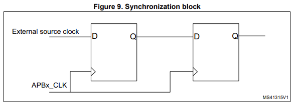
As described in AN4776, external clock sources are re-synchronized on all inputs, as shown in the figure above.
This would limit the maximum counting frequency to about one third of APBx_CLK.
The MCU onboard of the NUCLEO-H743ZI2 has mask revision V and is capable of running on up to 240 MHz for the timer peripheral clock signal. For direct counting with an external clock signal, this would result in a frequency counting limit of about 80 MHz. For the older mask revision Y onboard of the NUCLEO-H743ZI, the limit would be 200 MHz/3 = 67 MHz.
ETR inputs are an exception to this: ETR inputs are equipped with prescalers/dividers, as can be seen in the next figure:
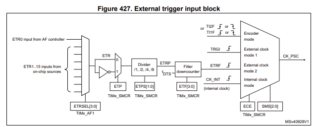
As input I use ETR2, which is available for Timer 2 as external input signal TIM2_ETR on MCU pin PA5.
For Timer 5, ETR2 is available as external input signal TIM5_ETR on pin PA4.
The interesting thing is that the divider/prescaler divides the signal BEFORE it gets re-synchronized and sampled by the internal timer peripheral clock signal. This means that by using the prescaler you can extend the maximum counting frequency by the division factor.
That means the following:
Without the prescaler, frequency counting is limited to about 80 MHz. With a divider ratio of 2 the upper limit rises to 160 Mhz, with a divider of 4 you get 320 MHz and with a divider of 8 you even get 640 MHz as upper limit.
I will not state that this really allows frequency counting up to 640 MHz in practice, of course not. There are number of factors that surely prevent this, e.g. the upper frequency limit of the divider itself, transmission line effects on the way from the pin via the lead frame of the MCU to the chip and some other factors, too.
But in practice it was at least possible for me to count LVTTL signals with 330 MHz, which I find quite remarkable.
The next thing one has to do is to configure TIM2 and TIM5 such that after a predefined time – this time will be given by another timer, TIM3 – the current Timer count value will be latched by an input capture register, and the counters will be reset after this event.
The last thing one has to do is to configure TIM3 to produce an event on a regular time base. This is what is usually called the gate time of the counter.
Detailed list of the configuration steps:
- Step 1:
- Set PA5 to Alternate Function TIM2_ETR and PA4 to Alternate Function TIM5_ETR
- Step 2:
- Configure TIM2 with STM32CubeIDE for External Clock and INPUT-CAPTURE-MODE with COMBINED RESET TRIGGER MODE in the following way:
- Slave Mode: Combined Reset Trigger Mode
- Trigger Source: ITR2
- Clock Source: ETR2
- Channel1: Input Capture triggered by TRC
- Counter Settings:
- Slave Mode Controller: Combined Reset Trigger Mode
- TRGO Parameters:
- Master/Slave Mode (MSM bit): Enable
- Trigger Event Selection: Reset
- Clock:
- Clock Prescaler: choose either „not used“ or 2 or 4 or 8, depending on max counting frequency!
- Input Capture Channel 1:
- IC Selection: TRC
- Prescaler Division Ratio: No division
- Do not forget to enable TIM2 Timer interrupt!
- Configure TIM2 with STM32CubeIDE for External Clock and INPUT-CAPTURE-MODE with COMBINED RESET TRIGGER MODE in the following way:
- Step 3:
- Configure TIM5 exactly like TIM2
- Do not forget to enable the TIM5 Timer interrupt!
- Step 4:
- Configure TIM3 in order to generate an UPDATE event on regular intervals of 1 sec (or whatever gate time you like):
- Clock Source: Internal Clock
- Counter Settings:
- Prescaler: 9999
- Counter Mode: Up
- Counter Period: 47999
- Internal Clock Division: No Division
- auto-reload preload: Disable
- Trigger Output (TRGO) Parameters:
- Master/Slave Mode (MSM bit): Enable
- Trigger Event Selection TRGO: Update Event
- Clock Source: Internal Clock
- Configure TIM3 in order to generate an UPDATE event on regular intervals of 1 sec (or whatever gate time you like):
If everything has been configured correctly, a TIM2- and a TIM5-interrupt occurs after each TIM3 timer event and the input capture registers of the used input channels of TIM2 and TIM5 contain the count values and can be read in the main loop.
Instead of using TIM3 for determining the measurement period for both counters TIM2 and TIM5, you could also use other counters for this. You just have to select other Trigger sources ITRn. For a list of possible trigger sources see the following figure:
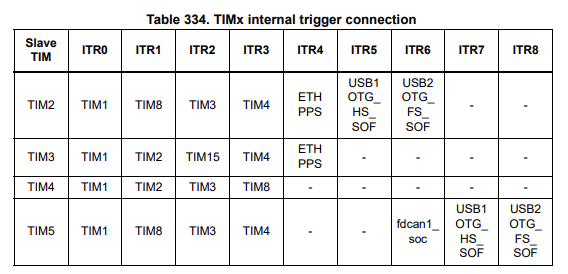
I haven’t tried it out yet, but by selecting different trigger sources, it should be perfectly possible to have two counters with different gate times.
If you want to try out counting with the H7, you can download the STM32Cube IDE project from here:
https://github.com/papamidas/H7CTR2CH
For testing the counter, you need a NUCLEO-H743ZI2 and a 40 MHz clock oscillator soldered to the board as MCU clock, like shown in my older blog entry. If you solder-in a clock oscillator with another frequency or just a quartz crystal, which would be perfectly fine, you have to change the clock configuration first before continuing.
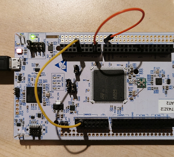
For a first test, you should connect MCO1 and MCO2 of the MCU
MCO1 is an alternate function of PA8 and can be found on CN12, which a little unconvenient, because this connector is not installed.
MCO2 is an alternate function of PC9 and can be found on CN8
Connect MCO1 and MCO2 to PA4 and PA5, repectively, like shown in this picture:
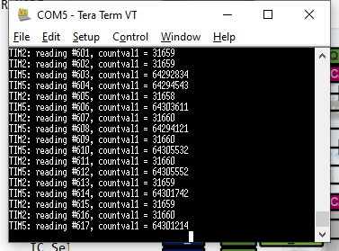
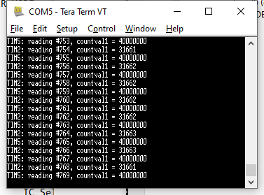
Because MCO1 is configured to output the internal HSI oscillator, which is about 64 MHz and MCO2 is configured to output the internal LSI oscillator, which is about 32 KHz, you should see an output on the virtual COM port like in the following screen dump:
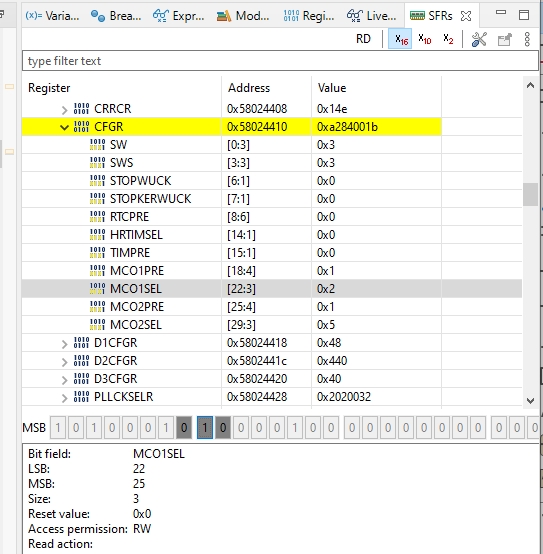
If you now press the PAUSE button of the debugger and select RCC -> CFGR -> MCO1SEL or RCC -> CFGR -> MCO2SEL, you can change the output signal of MCO1 or MCO2:
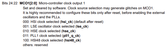
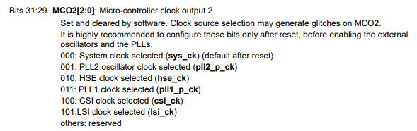
The possible selections are described in the register list in the reference manual RM0433 on page 387 of Rev 7:
If you now change MCO1 or MCO2 to some other output frequency that is derived from the same clock frequency that APBx_CLK is derived from, you should get pretty stable count values. As an example, the following screen dump shows the HSE frequency:
Now that you have tested the correct function of the 2-channel-frequency counter, you can connect an SI5351 board to the inputs.
For this I used an Adafruit SI5351 clock generator breakout board. In order to measure frequencies of up to a few hunderds of MHz, you should use really short wires for the connection between the SI5351 and the NUCLEO board. In the following picture you can see how I did it:
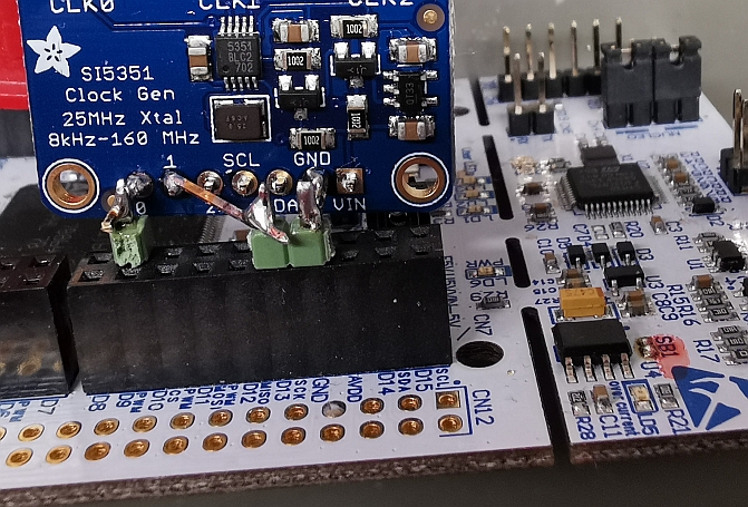
I used short pieces of brass header pins. These are much stiffer than copper wires and hold the breakout board in place without problems.
For controlling the SI5351, one has almost countless options.
I could have used the NUCLEO-H743ZI2 itself for controlling the SI5351, but I was lazy and used a Pyboard with Micropython running on it:
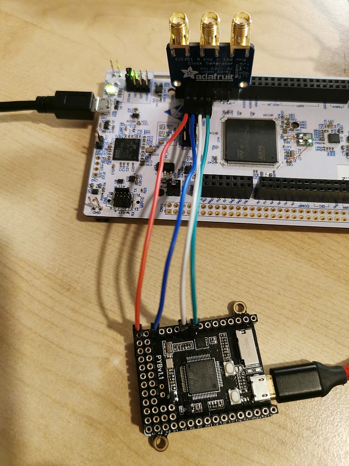
I used this Micropython port of the Arduino code of the Adafruit SI5351 breakout board for playing around with the settings of the SI5351.
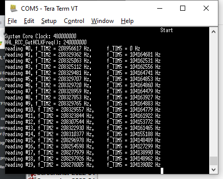
The following screendump shows the highest frequency that I could achieve on one of the SI5351 outputs: 208.33 MHz. The other output is configured for exactly one half of this frequency (104.17 MHz).
Have fun!